
Installation

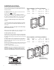
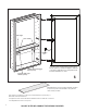

C. Install the cabinet with four (4) #10 x 1 1/2” wood screws (supplied).
Use the pre-punched holes above and below the hinge plates (as
shown). Do not overtighten. Cover screws with four screw caps (part
#434).
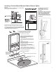
Electrician should
make the wire con-
nections and replace the Electric Option shelf’s front cover with the
three Allen screws provided. Make sure not to crimp or pinch the switch
wires and other electrical connections. (Refer to steps 1-5 on pages 5
for detailed diagrams).
TAKE CARE NOT TO SCRATCH THE INSIDE WALL OF THE
CABINET WITH THE EDGES OF THE SHELF COVER.
DO NOT ALTER ANY WIRING WITH THE ELECTRIC OPTION UNIT
OTHER THAN MAKING THE INITIAL CONNECTION.
7
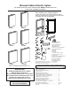
Installing a Recessed & Semi-Recessed
Mirrored Cabinet Electric Option
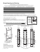
A. Determine the rough opening for the cabinet. Refer to “R.O.” formula
chart and diagrams on page 6. Opening must be plumb and level. In-
stall Electric Option rough wiring with at least 20” excess wire to
enable pull through from either the left of right wire access plastic
bushing installed in the cabinets. This unit requires a Class A 120V
AC 20 Amp GFCI circuit
breaker (Ground Fault Circuit
Interrupter) required by the
National Electric Code. All
Electric work must be pro-
vided by a Licensed Electri-
cian.
SPECIAL NOTE: When in-
stalling this cabinet over
the finished surface that
includes tile, the location
of the wire access hole
must be repositioned to
allow for the thickness of
the sheetrock and the tile.
B. Cabinet can be hinged on left or right. YOU MUST ORDER A LEFT
OR RIGHT HANDED DOOR AT THE TIME OF ORDER FOR ALL MIR-
RORED CABINET ELECTRIC OPTION UNITS.
For multiple cabinet units determine the hinge location for each unit
before they are joined together and mark the top of each unit.
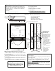
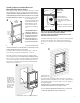
Remove the front panel of the Electric Option shelf using the Allen
wrench supplied. (DO NOT LOSE THE ALLEN SCREWS PROVIDED.)
(Refer to steps 1-2 on page 5 for detailed diagrams). Pull wire through
access. Insert cabinet in R.O. and center. Cabinet ange covers any
gaps in the R.O. around the cabinet and should overlap the nished
surfaces--sheetrock and/or tile.
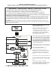
C
2x4
Framing
Shown
PLUMB
LEVEL
1
1
/2”
dia.
Wire
Access
Hole
11
5
/
8
”
11
5
/
8
”
A
B
Hinge Plate shown for right hinged door.
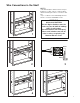
White Opal
Acrylic Shelf
LED Light
Plastic Bushing --
Wire push-through
(Side Access Shown)
Holds wire secure without
clamps.
(Rear Access Bushing-used
in surface mounted cabinets)
THE 1 1/2” ACCESS HOLE MUST BE ALIGNED EXACTLY WITH-
THE PLASTIC BUSHING TO PREVENT CRIMPING.
FOR EXACT DRILL LOCATIONS FOR THE ELECTRIC ACCESS
HOLE SEE DIAGRAMS ON PAGE 6
Rough wire for
this unit should
extend 20” from
either the left or
right wire access
on the side of the
cabinet to make
the connections
within the
Electric Shelf.