
Installation


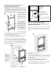

Tools Required for Installation
GlassCrafters recommends the following tools to
properly and safely install your Mirrored Cabinets.
A. Safety Glasses -- should be worn at all times
B. Tape Measure
C. Level
D. #2 Phillips Head Screw Driver
E. Power Screw Driver
F. Electric Drill
G. 8mm 3/16” Masonry Drill Bit
H. 7/32” Drill Bit
I. Non Ammonia Household Glass Cleaner
J. Soft Paper Towels
3
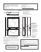
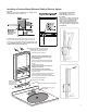
• This unit has a complete Electrical Shelf with light and outlets
factory installed.
• Do not attempt to repair or change any connections within the
Electric Option shelf.
• The 45 Watt Door heater/defogger plugs into the Electric Op-
tion shelf. The Door is equipped with a connect cord on the
hinge side. The left or right hand orientation of the door must be
determined at the time of order.
Add “EL” or “ER” to the model code on this product. See Price
Sheet for model code directions.
• The Electric Option is available with frameless or framed mirror
cabinets.
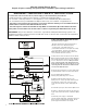
Electric Option Features:
• 2 Electrical AC Outlets
• Integral LED Light
• Heated Door Defogger
• Illuminated Indicator Switches
Electric
Access
Plastic
Bushing
LED
Light
Strip
LED
Light
Strip
3/4” Front Flange overlaps nished surfaces
White
Opal
Acrylic
Shelf
Rear
Electric Access
for
Surface Mount
5”
Cabinet shown open
without the door
for Electric Option details
Defogger
connector
Defogger
outlets
Outlet
110V
Outlet
110V
Defogger
Switch
Blue Light
LED Light
Switch
White Light
Electric Shelf:
2 7/8” deep
for both 4” &
6” cabinets
White Opal Acrylic Shelf
LED
Light
Strip
2
1
/
2
”+
11
5
/
8
”
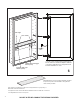
17 1/2”
5 7/8”
3 7/8”
4
1
/
2
”+
Center
line for
access hole
from
nished
surface -
including
sheetrock
& tile.
(1 1/2” dia)
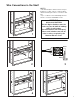
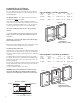
NOTE: For Electric Wiring Instructions see page 6.
• All Electric Option units for all 30” and 36” height cabinets --
16”, 20” & 24” wide --are factory installed at the same height
above the cabinet base.
• Electric Access pull through location is also in the same posi-
tion for all sizes.
• The Electric Option details shown here are common to all
sizes and models.
• All wiring should be done by a qualified licensed electrician
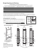
Diagram EL1
All wiring should be done by a
qualified licensed electrician in
a manner that conforms to the
National Electric Code.
Shown here is the
Electric Access
Plastic Bushing.
The dimensions indicate
the set back from the
finished surface of the
access hole in the stud
wall which must align
exactly with the
Plastic Bushing.
If the finished surface is
to include tile or any
decorative wall finish in
addition to the 1/2”
sheetrock over the studs,
then the center point for
the 1 1/2” dia access
hole is at:
2 1/2” for 4” recessed
or
4 1/2” for 6” recessed
and
must include the
thickness of those
additional planned
surface finishes
such as tile.