User’s Manual Single Board Computer 3301630 Version 1.
Copyrights This manual is copyrighted and all rights are reserved. It does not allow any non authorization in copied, photocopied, translated or reproduced to any electronic or machine readable form in whole or in part without prior written consent from the manufacturer.
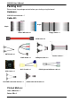
301630 User’s Manual Packing List: Please check the package content before you starting using the board.
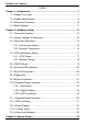
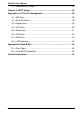
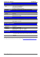
3301630 User’s Manual Index Chapter 1 ............................................................................ 7 1.1 .......................................................................... 7 1.2 ..................................................................... 8 1.3 .................................................................... 10 1.4 ..............................................................
3301630 User’s Manual 3.1
3301630 User’s Manual (This Page is Left for Blank) 6
3301630 User’s Manual Introduction Chapter 1 1.1 3301630 is the new generation of the Half-size PCI CPU card, with supporting last Intel Pentium M processors for 533MHz front side bus, Intel 915GM and ICH6-M chipset, integrated GMA900 graphics, DDR2 memory, REALTEK AC97 Audio, Serial ATA, mini PCI and dual Gigabit LAN.
3301630 User’s Manual Introduction 1.
3301630 User’s Manual Introduction Ethernet Interface Controller Marvell 88E8053 PCI Express Gigabit Ethernet controller Type Triple speed 10/100/1000Base-T auto-switching Fast Ethernet Full duplex, IEEE802.
3301630 User’s Manual Introduction 1.
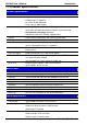
3301630 User’s Manual Introduction 1.4 Intel Pentium M/Celeron M Processors Intel GMA900 Graphics LVDS 2 x 240-pin DDR2 DVI SDVO 400/533MHz up to 915GM 2GB HDTV CompactFlash 2 x Serial ATA ports UltraDMA33/66/100 IDE ICH6-M 2 x USB2.
3301630 User’s Manual (This Page is Left for Blank) 12
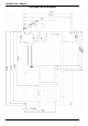
3301630 User’s Manual Hardware Setup Chapter 2 2.
3301630 User’s Manual CF 14
3301630 User’s Manual Hardware Setup 2.
3301630 User’s Manual Hardware Setup 2.3 2.3.
3301630 User’s Manual Hardware Setup 2.4 2.4.1 The board comes with the socket479 for Intel Pentium M/Celeron M processors, it supports new generation of Intel Pentium M processors with 533MHz of front side bus and 2MB L2 cache. Please follow the instruction to install the CPU properly. Check point Unlock way 1. Use the flat-type screw drive to unlock the CPU socket 2. Follow the pin direction to install the processor on the socket 3.
3301630 User’s Manual Hardware Setup 2.4.2 The board provides two 240-pin DDR2 DIMMs to support DDR2 400/533 memory modules up to 2GB of capacity. Non-ECC, unbuffered memory is supported only. While applying two same modules, dual channel technology is enabled automatically for higher performance. DDRIIB/A Please check the pin number to match the socket side well before installing memory module.
3301630 User’s Manual Hardware Setup 2.5 The board’s data of CMOS can be setting in BIOS. If the board refuses to boot due to inappropriate CMOS settings, here is how to proceed to clear (reset) the CMOS to its default values.
3301630 User’s Manual Hardware Setup 2.6 The board has one UltraDMA33 IDE interface to support up to 2 ATAPI devices, and one CompactFlash Type II socket on the solder side, with jumper JCFSEL for IDE master/slave mode selection. Jumper: JCFSEL Type: onboard 3-pin header JCFSEL Mode 1-2 Master 2-3 Slave Default setting 1 3 JCFSEL 2.7 Based on Intel ICH6-M, the board provides two Serial ATA interfaces with up to 150MB/s of transfer rate.
3301630 User’s Manual Hardware Setup 2.8 The board provides one standard type floppy port.
3301630 User’s Manual Hardware Setup 2.9 The board integrates with two Marvell 88E8053 PCI Express Gigabit Ethernet controllers, as the PCI Express 1x can speed up to 250MB/s of transfer rate instead of late PCI bus with 133MB/s of transfer rate. The Marvell 88E8053 supports triple speed of 10/100/100Base-T, with IEEE802.3 compliance and Wake-On-LAN supported.
3301630 User’s Manual Hardware Setup 2.10 Based on Intel 915GM chipset with built-in GMA (Graphic Media Accelerator) 900 graphics, the board provides one DVI connector on real external I/O port, and one 40-pin LVDS interface with 5-pin LCD backlight inverter connector. The board provides dual display function with clone mode and extended desktop mode for CRT,DVI,LCD and TV 2.10.
3301630 User’s Manual Hardware Setup 2.10.2 The board provides one 40-pin LVDS connector for 24-bit single/dual channel panels, supports up to 1600 x 1200 (UXGA) and 1920 x 1200 (WUXGA) of resolution, with one LCD backlight inverter connector and one jumper for panel voltage setting.
3301630 User’s Manual Connector: CN_INV Type: 5-pin LVDS Power Header Pin Description 1 +12V 2 GND 3 GND 4 GND 5 ENABKL Hardware Setup Connector: JVLCD2 Type: 3-pin Power select Header Pin Description 1 VCC 2 LCDVCC 3 VCC3 Connector: CN_LVDS2 Type: onboard 40-pin connector for LVDS connector Connector model: HIROSE DF13-40DP-1.
3301630 User’s Manual Hardware Setup To setup the LCD, you need the component below: 1. A panel with LVDS interfaces. 2. An inverter for panel’s backlight power. 3. A LCD cable and an inverter cable. For the cables, please follow the pin assignment of the connector to make a cable, because every panel has its own pin assignment, so we do not provide a standard cable; please find a local cable manufacture to make cables. LCD Installation Guide: 1.
3301630 User’s Manual Hardware Setup After setup the devices well, you need to select the LCD panel type in the BIOS. The panel type mapping is list below: 3301630 BIOS LCD Type selection form Single channel 18bit (VER:1.0S18A) Dual channel 18bit (VER:1.0D18A) NO. Output format NO. 1 640 x 480 1 2 800 x 600 2 3 1024 x 768 3 4 1280 x 768 4 Single channel 24bit (VER:1.0S24A) Output format Dual channel 24bit (VER:1.0D24A) NO. Output format NO.
3301630 User’s Manual Hardware Setup 2.10.3 The board provides output types with Composite, S-Video and Component (YPbPr) Composite and S-Video up to 1024 x 768 for NTSC/PAL Component support 480p/720p/1080i/1080p mode Connector: CN_TV Connector type: 8-pin header TV-out connector (pitch = 2.
3301630 User’s Manual Hardware Setup 2.11 3301630 provides a stereo audio interface with Realtek ALC201A AC97 Codec. The CN_AUDIO provides the interface to use attached audio cable, the CDIN can let you connect audio output from CD-ROM drives.
3301630 User’s Manual Connector: CN_AUDIO Type: 10-pin (2 x 5) 2.
3301630 User’s Manual Hardware Setup 2.12 The board provides a programmable 8-bit digital I/O interface; you can use this general purpose I/O port for system control like POS or KIOSK. Connector: CN_DIO Type: 12-pin (6 x 2) 2.0mm x 2.
3301630 User’s Manual Hardware Setup 2.13 2.13.1 The board requires DC 12V/5V input with onboard 4-pin connector, for the input current, please take a reference of the power consumption report on appendix.
01630 User’s Manual Hardware Setup 2.14 The JFRNT provides front control panel of the board, such as power button, reset and beeper, etc. Please check well before you connecting the cables on the chassis. Connector: JFRNT Type: onboard 14-pin (2 x 7) 2.
3301630 User’s Manual Hardware Setup Chapter 3 3.1
3301630 User’s Manual System Setup Fixed + DVMT Memory Size: You can select the fixed amount and the DVMT amount at the same time for a guaranteed video memory and additional dynamic video memory, please check the table below for available setting.
3301630 User’s Manual System Setup Chapter 4 The motherboard uses the Award BIOS for the system configuration. The Award BIOS in the single board computer is a customized version of the industrial standard BIOS for IBM PC AT-compatible computers. It supports Intel x86 and compatible CPU architecture based processors and computers. The BIOS provides critical low-level support for the system central processing, memory and I/O sub-systems.
3301630 User’s Manual BIOS Setup (This Page is Left for Blank) BIOS Setup 37
3301630 User’s Manual Appendix A A.
3301630 User’s Manual I/O Port Pin Assignment A.2 Connector: SATA1/2 Type: 7-pin wafer connector 1 2 3 4 5 6 7 GND RSATA_TXP1 RSATA_TXN1 GND RSATA_RXN1 RSATA_RXP1 GND A.
3301630 User’s Manual I/O Port Pin Assignment A.
3301630 User’s Manual I/O Port Pin Assignment A.5 Connector: CN_COM12/CN_COM34 Type: 20-pin (10 x 2) 1.27mm x 2.
3301630 User’s Manual Hardware Setup 2.4 2.4.1 The board comes with the socket479 for Intel Pentium M/Celeron M processors, it supports new generation of Intel Pentium M processors with 533MHz of front side bus and 2MB L2 cache. Please follow the instruction to install the CPU properly. Check point Unlock way 1. Use the flat-type screw drive to unlock the CPU socket 2. Follow the pin direction to install the processor on the socket 3.
3301630 User’s Manual Flash BIOS Appendix B B.1 The board is based on Award BIOS and can be updated easily by the BIOS auto flash tool. You can download the tool online at the address below: http://www.phoenix.com/en/home/ File name of the tool is “awdflash.exe”, it’s the utility that can write the data into the BIOS flash ship and update the BIOS. B.2 1. Please make a bootable floppy disk. 2. Get the last .
Any advice or comments about our products and service, or anything we can help you with please don’t hesitate to contact us. We will do our best to support your products, projects and business. Address: Global American, Inc. 17 Hampshire Drive Hudson, NH 03051 Telephone: Toll Free (U.S. Only) 800-833-8999 (603)886-3900 FAX: (603)886-4545 Website: Support: http://www.globalamericaninc.