
User's Manual


This document and information herein is the property of Global Display Solutions and all unauthorised use and
reproduction is prohibited. Copyright © 2012 by Global Display Solutions, Italy. All rights reserved. Confidential,
Unpublished Property of GDS.
MAN10408_00 6 of 8
5. Connections
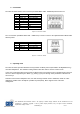
The NFC 12V board has the main connector (Picoblade Molex SMT - 53398-087) with reference J9.
Pin
Function
Description
1
+12Vdc
Power Supply
2
RS232_TX
Serial Data Out
3
RS232_RX
Serial Data In
4
RTS out
RTS out
5
CTS in
CTS in
6
Relè out
Relè out
7
NC
NC
8
GND
Ground
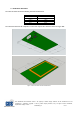
Figure 2 J9 connector details
The J2 connection (Picoblade Molex SMT - 53398-0471) is used to connect e the optional Remote Mifare Board
with this pinout:
Pin
Function
Description
1
+3.3Vdc
Power Supply
2
GND
Ground
3
UART_TX
Serial Data Out
4
UART_RX
Serial Data In
Figure 3: J2 connector details
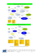
6. Operating mode
The NFC 12V board operates with both user keys based on Mifare protocol (TGS Mifare and MyWellness key)
and NFC smartphones. The minimum reading distance with NFC devices must be at least 15 mm.
In the case of interaction with user key based on Mifare protocol, the board traces its operating states, based on
the use of fitness equipment by the athlete (eg, running a year) and through some parameters collected from
the user keys.
When the board reads a smartphone NFC, the data exchange between them is minimized, thanks to a NFC
application, installed in the smartphone (installed as prerequisite), which supports most of the data
management.