globalindustrial.ca Distribucion Industrial Globales S DE RL DE CF Assembly Instructions Instrucciones de Ensamblaje Directives d’assemblage Customer Service US: 1-800-645-2986 Servicio de atención al Cliente México: 01.800.681.
Assembly Instructions Salamander Electric BlowerHeater Heater IMPORTANT INSTRUCTIONS 6. Do not use outdoors. 7. To disconnect heater, turn off power circuit at main disconnect panel. 8. For wall or ceiling installation, do not install less than 8 6 feet (1.8m) (1.2m) (2.4 m) high from floor and closer than 41 feet foot (0.3 m) to any adjacent vertical surfaces or walls. Keep at least 4.5 inches (11.5 cm) from back wall (with or without wall hanging mounting bracket). 9.
Assembly Instructions User’s Manual Salamander Electric BlowerHeater Heater Wiring Diagrams L1 L2 G 653558 653558 240V/60Hz/1P 10KW Overheat Protection L1 L2 G L1 L2 L3 G Motor Tip over switch L1 L2 L3 G Motor 653568 653561 653561 653671 240V/60Hz/3P 15KW Thermostat Light Tip over switch Fan Switch 653569 653562 653562 653672 480V/60Hz/3P 15KW L1 L2 L3 G Motor Fan Switch 246067 653674 246067 246068 480V/60Hz/3P 30KW Overheat Protection Thermostat Motor Fan Switch Overheat Protectio
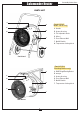
Salamander Electric BlowerHeater Heater Assembly Instructions PARTS LIST G A F B E C (Part# 653565, Mobile cart kit only) A. Handle B. Heater Housing C. Tilt Adjustable Knob D. Wheel E. Front Exhaust Grill F. On/Off Switch G. Temperature Setting Knob D Cart-Stand (Part# 653564, Mounting Bracket only) A F E B D C Wall Mount 4 A. Wall/Ceiling Wall MountMounting BracketBracket B. Hanger C. Heater Housing D. Front Exhaust Grill E. On/Off Switch F.
Assembly Instructions User’s Manual Electric BlowerHeater Heater Salamander CART INSTALLATION INSTRUCTION INSTALLATION INSTRUCTIONS CAUTION WARNING Keep electrical cords, drapery, furnishings and other combustibles at least 3 feet (0.9 m) from heater, to prevent risk of fire. All wiring must be installed by a certified electrician in accordance with electrical safety standards. All wiring procedures and connections must be in accordance with national and local codes.
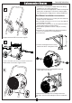
Salamander Heater Assembly Instructions 6.Connect the electrical power supply cable to the wiring compartment. (See wiring instructions). Attach connectors to the appropriate conductor and ground wiring. After completing the connections, arrange pigtail unit leads and power supply wires in wiring compartment. 4 Wall Mount Installation Instructions: 10 10 9 9 8 9 9 8 1. Keep unit at least 6 feet (1.8 m) away from floor. Minimum distance must be maintained. 2.
Assembly Instructions Heater Electric Salamander BlowerHeater 10. Connect the electrical power supply cable in flexible conduit to wiring compartment. 11. Attach with connectors suitable for conductor size and ground wiring. After completing the connections, arrange pigtail unit leads and power supply wires in wiring compartment. OPERATING INSTRUCTIONS HAZARD OF ELECTRIC SHOCK, EXPLOSION OR ARC FLASH: • Apply appropriate personal protective equipment (PPE) and follow safe electrical work practices.
User’s Manual Salamander Electric BlowerHeater Heater WIRING INSTRUCTIONS For Models Model 653560 For 653558, 653670 & 653567 1. Open the compartment. L2 L1 2. Connect the live wires to L1 and L2 of the terminal block. Connect ground wire to . 3. Close compartment. Note: Use wire terminal crimp when connecting to terminals.
g lobalindustrial.ca Distribucion Industrial Globales S DE RL DE CF Assembly Instructions Instrucciones de Ensambla aje Directives d’assemblage Customer Service US: 1-800-645-2986 Servicio de atención al Clien nte México: 01.800.681.
Calentador DeAire Salamandra Calentador De Eléctrico Instrucciones de Ensamblaje INSTRUCCIONES DE IMPORTANCIA 6. No utilice el calentador en exteriores 7. Para desconectar el calentador, corte la corriente en el panel principal de desconexión. 8. Para instalar el calentador en el techo o la pared, no lo sitúe a menos de 2,4 1,8 m de altura desde el suelo y a menos de 30 1,2cm para las superficies adyacentes verticales o paredes.
Instrucciones de Ensamblaje Calentador DeAire Salamandra Calentador De Eléctrico Instrucciones de Ensamblaje Diagramas de Cableado L1 653558 653558 240V/60Hz/1P 10KW L2 G G El poder del bloque de terminales Protección Sobrecalentamiento Protección Protección Sobrecalentamiento Sobrecalentamiento Termostato Termostato Protección Sobrecalentamiento Motor Luz Luz G 653670 653567 653560 653560 240V/60Hz/1P 15KW G Protección Protección Sobrecalentamiento Sobrecalentamiento Termostato Termosta
Calentador DeAire Salamandra Calentador De Eléctrico Instrucciones de Ensamblaje LISTA PARTES G A F B E C (Part# 653565, Solo kit de carro móvil) A. Manilla B. Carcasa Calentador C. Perilla Ajuste Inclinación D. Rueda E. Rejilla Escape Frontal F. Conmutador On/Off G. Perilla Configuración Temperatura D Pedestal Carro A F E B D C Instalación Mural 4 (Part# 653564, Solo soporte de montaje) de pared para techo A. Soporte mural B. Colgador C. Carcasa Calentador D. Rejilla Escape Frontal E.
Manual del usuario CalentadorDe DeAire Salamandra Calentador Eléctrico INSTRUCCION DE INSTALACIÓN DE CARRO ! ! PRECAUCIÓN Mantenga los cables eléctricos, cortinas, muebles y otros combustibles por lo menos 3 pies (0,9 m) de calentador, para prevenir el riesgo de incendio. ADVERTENCIA Todo el cableado debe ser instalado por un técnico electricista certificado, en conformidad con los estándares de seguridad eléctrica.
CalentadorDe DeAire Salamandra Calentador Eléctrico Manual del usuario 6.Conecte el cable de suministro de energía eléctrica al compartimiento de cableado (ver instrucciones de cableado).Fije los conectores al conductor y cableado de tierra apropiados. Después de completar las conexiones, organice los conectores y los cables de alimentación en el compartimiento de cableado. 4 Instrucciones de instalación para el montaje en pared: 10 10 9 9 8 9 9 8 4.
Manual del usuario CalentadorDe DeAire Salamandra Calentador Eléctrico 10. Conecte el cable del suministro de energía eléctrica en el conducto flexible al compartimiento del cableado. 11. Fije con los conectores adecuados al tamaño del conductor y al cableado de tierra. Después de c ompletar las conexiones, organice los conectores y los cables del suministro de energía en el compartimiento de cableado. 2.Identifique el corte térmico de restablecimiento manual con el botón cuadrado rojo como sigue.
Calentador DeAire Salamandra Calentador De Eléctrico Instrucciones de Ensamblaje INSTRUCCIONES DE CABLEADO Modelo Modelos653560 653558, 653670 & 653567 1. Abra el compartimento. L2 L1 2. Conecte los cables con corriente a L1 y L2 del bloque de terminales. Conecte el cable de tierra a . L1: Cable blanco con corriente L2: Cable negro con corriente 3. Cierre el compartimento. Nota: utilice una crimpadora de terminales de cables para conectar las terminales.
g lobalindustrial.ca Distribucion Industrial Globales S DE RL DE CF Assembly Instructions Instrucciones de Ensambla aje Directives d’assemblage Customer Service US: 1-800-645-2986 Servicio de atención al Clien nte México: 01.800.681.
Directives d’assemblage Chauffe Salamandre Ventilateur Électrique Chauffant INSTRUCTIONS IMPORTANTES 6. Ne pas utiliser à l’extérieur. 7. Pour débrancher le réchauffeur, coupez l’alimentation du circuit au niveau du panneau de déconnexion principal. 8. Pour installation au mur ou au plafond, ne pas installer pas moins de 68 pieds (2,4 (0,3 m) des surfaces 1,8 m) de hauteur à partir du sol et à moins de 14 pied (1,2m) verticales adjacentes ou des murs.
Directives d’assemblage Directives d’assemblage ChauffeÉlectrique Salamandre Ventilateur Chauffant Wiring Diagrams L1 653558 653558 240V/60Hz/1P 10KW L2 G G Power terminal block Protection contre Protection la surchauffe contre Protection Protection contre contre la la surchauffe surchauffe Thermostat Thermostat la surchauffe Moteur Lumière Lumière Lumière Commutateur Fan Commutateur Fan Tip-commutateur Commutateur Fan G 653670 653560 653567 653567 653560 240V/60Hz/1P 15KW G Protection
Chauffe Salamandre Ventilateur Électrique Chauffant Directives d’assemblage LISTE DES PIÈCES G A F B E C (Part# 653565, Kit de chariot mobile uniquement) A. Poignée B. Boitier du réchauffeur C. Inclinez bouton réglable D. Roue E. Échappement avant de la grille F. Interrupteur ON/OFF G Bouton de réglage température D Montage de panier A F E B D C Montage mural 4 (Part# 653564, Support de montage uniquement) plafond mural A. Support de mural B. Crochet C. Boitier du réchauffeur D. Roue E.
Directives d’assemblage Ventilateur Électrique Chauffant Chauffe Salamandre INSTRUCTIONS D'INSTALLATION DE CHARIOT ! ! MISE EN GARDE Gardez les cordons électriques, draperie, meubles et autres combustibles au moins 3 pieds (0,9 m) du réchauffeur, pour prévenir le risque d'incendie. AVERTISSEMENT Tout le câblage doit être installé par un électricien certifié conformément aux normes de sécurité électrique.
Ventilateur Électrique Chauffant Chauffe Salamandre Directives d’assemblage 6.Connectez le câble d’alimentation électrique au compartiment de câblage. (Voir les instructions de câblage). Fixer les connecteurs aux conducteurs et câblages de masse. Après avoir effectué les connexions, organiser les connexions et les fils d’alimentation dans l’habitacle de câblage. 4 Instructions d’installation pour montage mural : 10 10 9 9 8 9 9 8 1. Laissez l’unité à au moins 6 pieds (1,8 m) du sol.
Directives d’assemblage Ventilateur Électrique Chauffant Chauffe Salamandre 10. Brancher le câble d’alimentation électrique dans le conduit flexible au compartiment de câblage. 11. Fixer avec les connecteurs adaptés à la taille du conducteur et au câblage de masse. Après avoir effectué les connexions, organiser les connexions de l’unité et diriger les fils d’alimentation dans l’habitacle du câblage. 2.Identifiez la coupure thermique à réinitialisation manuelle avec le bouton carré rouge comme suit.
Chauffe Salamandre Ventilateur Électrique Chauffant Directives d’assemblage INSTRUCTIONS DE CÂBLAGE Modèle 653560 Modèles 653558, 653670 & 653567 1. Ouvrir le compartiment. L2 L1 2. Brancher les fils sous tension à L1 et L2 du bornier. Connecter le fil de masse au . 3. Fermez le compartiment. Remarque : Utilisez un outil de sertissage lors de la connexion aux bornes.