1504 Isolated Variable AC Line Supply Instruction Manual Revision: 11/2010
TABLE OF CONTENTS INTRODUCTION PAGE 1 INITIAL INSPECTION PAGE 2 SPECIFICATIONS PAGE 3 DESCRIPTION PAGE 4 OPERATING INSTRUCTIONS PAGE 5 PART LIST & SCHEMATICS PAGE 6 CIRCUIT DIAGRAM PAGE SERVICE & WARRANTY PAGE
INTRODUCTION ISOLATED VARIABLE AC LINE SUPPLY : MODEL1504 The 1504 Isolated Variable AC Source cum leakage current tester is designed for modern electronics laboratories which need a clean, electrostatically and galvanically isolated variable line supply. The unit is designed to provide isolated output variable from 0 to 150 V AC/4 Amps Max. The output voltage and load current can be monitored on a 3 digit DPM.
INITIAL INSPECTION Before shipping, the 1504 power supply has been tested thoroughly and found free of mechanical and electrical defects. As soon as it is unpacked, inspect for any damage that may have occurred during transit. Particular attention should be paid to the meters. Also check the packing material for any signs of severe stress (may be indicative of internal damage). Save all the packing material.
SPECIFICATIONS OUTPUT VOLTAGE : 0 to 150 VAC INPUT VOLTAGE : 115 VAC ±10% INPUT FREQUENCY : 47 to 63 Hz. METERING : 3 digit DPM to read 1) Output Voltage. 2) Load Current and 3) Leakage current upto 9.99 mA. METER ACCURACY : ± 3 counts. OUTPUT-LINE ISOLATION : Capacitive coupling less than 0.0005 pF. LINE & OUTPUT LEAKAGE : NOISE REJECTION : Better than 120 db (common mode noise). DIMENSIONS : 298 mm(W) x 133 mm(H) x 270 mm(D) WEIGHT : 16 kgs. Less than 10 mA.
DESCRIPTION INPUT AND OUTPUT TERMINATION : The unit works from 115 V AC/47-63 Hz single phase supply. The input is provided through a mains cable with a three pin plug. The use of a three core cable enables the cabinet of the unit to be properly grounded. Output is provided on a three-pin socket and is clearly marked 0-150 V AC/4 Amps max.
OPERATING INSTRUCTIONS TURN ON PROCEDURE : a) 1504 as Isolated Variable Ac Supply. Set output voltage to ‘O’ volt by turning the knob to minimum position. Depress push switch marked ‘V’. Set power on switch. Adjust the voltage control till the desired voltage is indicated on the 3-digit DPM. Connect the load at the output. Depress push switch marked A. The DPM will now read the load current. The total load current should not exceed 4 Amps for continuous operation. b) 1504 as Line Leakage Tester.
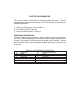
PART LIST & SCHEMATICS This section contains information for ordering replacement parts. Part list describes parts by reference designator used in circuit diagram & provides the following information : a) Reference Designators, refer to Table 4.1 b) Description Refer to Table 4.2 c) Location indicator Refer to Table 4.3 ORDERING INFORMATION To order replacement parts address order or enquiry to your local agent or ourselves.
TABLE 4.2 DESCRIPTION ABBREVIATION CD MP TAN SM ML ELEC mF CERAMIC DISC METALISED POLYESTER TANTALUM SILVER MICA MULTILAYER ELECTROLYTIC MICRO FARAD MFR CFR HVR K M E mH METAL FILM RESISTOR CARBON FILM RESISTOR HIGH VOLTAGE RESISTOR KILO MEGA OHM MILLI HENRY pF WW PICO FARAD WIRE WOUND mH MO MICRO HENRY METAL OXIDE TABLE 4.
SERVICE AND WARRANTY INFORMATION FACTORY SERVICE AND REPAIR Global Specialties will service and repair this instrument free of charge for a period of one full year, subject to the warranty conditions stated below. To obtain a return merchandise authorisation (RMA) required for all returns, phone our Customer Service Department for a RMA and all shipping instructions : Tel. 800-572-1028 or write : GLOBAL SPECIALTIES 22820 Savi Ranch Parkway Yorba Linda, 92887 TEL.: (203) 466 6103 FAX.
Ò and TM trademarks are the property of INTERPLEX ELECTRONICS, INC, New Haven, CT, 1994. CASE DISASSEMBLY AND ASSEMBLY WARNING Potentially lethal AC power is present whenever the line cord is plugged into the AC outlet, even when the power switch is OFF. Always disconnect the power cord when opening the case. Avoid touching the fuse post on the inside of the unit. Should access to the inside of the unit be required, proceed as follows : 1. Remove the line cord from the AC outlet before disassembly. 2.
RESISTORS : All resistors are 0.25W, +/- 5%, MFR unless otherwise specified. Reference Part Designator Descrip- Location Key Reference Designator tion Part Descrip- Location Key tion R1 1.3K 1 R1 39K 3 R2 91E 1 R2 470K 3 R3 1K 1 R3 1M 3 R4 7.5K 1 R4 Not used 3 R5 SHORT- 1 R5 2.4K 3 1 R6 2.7K 3 1 R7 39K 3 ING LINK R6 SHORTING LINK R7 SHORTING LINK R1 10k 2 R8 8.2K 3 R2 Not used 2 R9 100E 3 R3 10M 2 R10 12K 3 R4 100K 2 R11 20K 3 R5 8.
Designator Descrip- Key Designator tion Descrip- Key tion CAPACITORS (CD +/- 20%, TAN +/- 10%, SM +/- 5%, ELEC +/- 20% unless otherwise specified) C1 220mf 2 C4 ELEC 0.47mf 3 MP100V 50V C2 220mf 2 C5 ELEC 0.22mf 3 MP100V 16V C3 0.1mf MP 2 C6 100V C4 1mf ELEC 2 C7 0.22mf MP 2 1mf ELEC C8 220pf CD 3 0.1mf 3 CD 50V 2 C9 50V C1 0.1mf MP100V 100V C6 3 EC 50V 50V C5 10mf EL- Not 3 Used 3 C10 100V 470mf 3 ELEC 25V C2 0.1mf MP 3 C11 100V 2.
Designator Descrip- Key Designator tion Descrip- Key tion DIODES D1 1N4148 2 D1 1N4148 3 D2 1N4148 2 D2 1N4148 3 CR1 1N4003 1 D3 TO D6 1N4003 3 Q3 LM7805 3 2 TRANSISTORS/FET’S Q1 TL430 3 Q2 MPSA12 3 IC1 ICL 7660 2 IC3 CA3160 IC2 LM 741 2 U1 LM7107 3mm 3 LED2 3mm IC’S LED’S LED1 GREEN 3 GREEN FND’S DS1 LT542 3 DS3 LT542 3 DS2 LT542 3 DS4 LT542 3 Reference Part Designator Descrip- Location Key Reference Designator Part Descrip- Location Key
tion tion SWITCHES SW1 TO SW3 4 Pole 1 SW4 2WAY 1801 7 ON/OFF TRANSFORMERS T1 Isolation 6 T3 DPM 6 T2 Current 6 T4 0-120V/ 7 4A Variable FUSE F1 8Amp 7 2/P 2CO 1 RELAY RL1 6V/6A