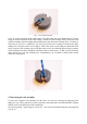
1 Basic description of the design The minesweeper extension will enable the ASURO robot to detect metallic objects underneath the halved Ping-pong ball-glider. This will allow you – of course within the scope of the robot's and the kit's possibilities - to develop the scenario of a robotic mine detector respectively treasury hunter or a simplified version of a detector and tracer for cables, reinforcing bars and I-beams.
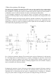
To achieve this goal, the design controls the capacitor's current proportionally to the capacitor's voltage. In this system the active element is the operational amplifier IC1A in a non-inverting amplifier circuit with resistor R2 and the trimmer resistor TR1. This circuit will amplify the capacitor's voltage at an adjustable rate of 1 up to 3, which will increase the current into resistor R1 proportionally to the voltage at C1.
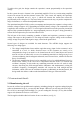
Figure 2: coil-carrier, complete Figure 3: coil-carrier, halved In order to fit for our purposes, we will have to split up the carrier with a saw. A suitable saw for this is a fine-tooth hacksaw. We will have to remove one chamber by sawing the other chamber in the middle. This procedure results in a singular coil-carrier. Remaining sawing edges can be removed with fine sandpaper (grain size: 240 or 300) or by carefully using a sharp knife (protect your fingers!).
You may also cut the wire, but do not forget to reserve a few centimetres at both sides. The wireendings have to be directed into one direction and are not allowed to pass through the hole in the coil-carrier (see fig. 5). Fig. 5: coil-carrier - completed Having completed the coil-carrier, you can fix the structure into the core with some instant glue. The wire's endings are to leave the core at the closed core-side through a slit (see fig. 6). Fig.
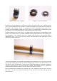
Fig. 7: Coil with capacitor Next, we proceed with the ready-made cables. The dual cable has been dimensioned at 70 mm, stripped, twined and tinned at the cable-endings. Solder the cable-endings directly entwined to the capacitor-endings with the endings and pointing in the same direction as shown in fig. 8. Polarity is irrelevant. If you have a multimeter you may now measure the resistance between both cableendings. The resistance-value is to be approx. 30Ω.
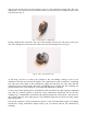
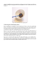
Attention: If ASURO has not been prepared for assembling an extension PC-board, you will have to postpone attaching the ping-pong ball until the preparation for the extension board has been completed. Fig. 9: Coil - attached to the ping-pong ball 2.3 Inserting the extended plug sockets Before assembling the components to the PC-board you will have to insert the extended plug sockets. You will have to use a different procedure depending on the status of the ASURO-system.
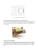
Fig. 10: Inserting the Extension-PCB b) ASURO already provides extended plug sockets for the extension board The two- and three-poled plug elements are to be inserted into the plugs at the ASURO-PC-board (see fig. 10), on top of which you attach the extension board. The pins will be protruding from the PCB. If all components are well-placed, the extended plug sockets are to be soldered to the extension board. Fig. 11: Extension board with extended plug sockets 2.
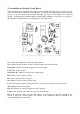
2.5 Assembling the Printed Circuit Board After placement of the extended plug sockets (and eventually the plug arrays as well), you may remove the PCB and complete the assembly phase. According to the component placement drawing (see fig. 12) you are advised to proceed the following way: Up to R7 all resistors are to be placed upright – according to the ASURO-standard, which implies bending a U-turn (180° ) for one leg of the components. Bend both legs for component R7 at an angle of 90°. Fig.
Fig. 13: Completed and placed Extension Board Note: Initially the terminals VCCOUT1/2, GNDOUT1/2 and ADC2OUT/ADC3OUT will not be needed. Additionally to the fixing hole at the PCB, these terminals may later be used to connect two distance sensors in a triangulation-sensor-system. This will allow the ASURO to apply an autonomous navigation system and to be searching metallic objects as well. For more details please consult “More Fun with ASURO, Volume II”.
while (count72kHz<100) { // Detect low level if ((PIND & (1<<2)) == 0) oscillation = TRUE; } // If oscillator is running, no metal object is within // range, so LED should be off if (oscillation) FrontLED(OFF); else FrontLED(ON); } } return 0; This program will switch off the LED as soon as the oscillator is working. Depending on the activated detection method (decay mode of the oscillations respectively variations of the oscillator frequency), we will need different calibration methods.
while(1) { freq=0; for (i=0; i<100; i++) { count72kHz=0; // This counter is incremented in timer interrupt FrontLED(OFF); while (count72kHz<72) { // Detect level change newlevel = PIND & (1<<2); if (oldlevel != newlevel) { oldlevel = newlevel; freq++; FrontLED(ON); } } } sprintf(s,"%5d\n\r",freq); SerWrite(s,7); } return 0; } 2.7 The debugging procedure If the system does not work as expected, we will have to start the debugging procedure.