PB-203A Powered Proto-Board Instruction Manual 10/2009
All rights reserved. No Part of this book shall be reproduced, stored in a retrieval system, or transmitted by any means, electronic, mechanical, photocopying recording, or otherwise, without written permission from the publisher. No patent liability is assumed with respect to the use of the information contained herein. While every precaution has been taken in the preparation of this book, the publisher assumes no responsibility for errors or omissions.
ABOUT GLOBAL SPECIALTIES Thank you for selecting this Global Specialties product. You won't be disappointed! Since 1973, Global Specialties has been the recognized leader in technical education courses, training equipment and tutorial materials. Our electronics and microcomputer teaching systems have proven to be effective in secondary schools, technical schools, colleges, universities and industrial training departments throughout the world.
TABLE OF CONTENTS Specifications ..........................................................................………..page 6 Operating Instructions ............................................................. ……….page 7 Power Supply Description & Schematic Diagram…………..………….page 9 Using the PB-203A .................................................................. ………page 10 Service & Warranty Information ..............................................
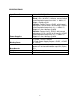
SPECIFICATIONS Input Power Source 108 to 130VAC @ 60Hz Power Supplies Fixed: +5V +/-0.2VDC, 1.0A max, current limited Load Regulation better than 0.8% +/- 0.02%/°C Ripple, <4mVp-p @1A Variable: Factory Set to +15VDC, with internal adjustment +5.5 to 18VDC, 0.5A max@ +15VDC Load Regulation better than 1% +/- 0.04%/°C, Ripple less that 10mVp-p @ 0.5A Variable: Factory Set to -15VDC, with internal adjustment -5.5 to -18VDC, 0.5A max@ +15VDC Load Regulation better than 1% +/- 0.
OPERATING INSTRUCTIONS Uncoil the power cord and plug the PB-203A into a 115V AC 60 Hz outlet. Push the power switch on. The power supply bank is now active, providing +5 Volts at 1 Amp for digital circuitry, and +15 and -15 Volt supplies at 0.5 Amp for linear and op-amp circuitry. All supplies are regulated and current limited for maximum performance and safety. The black binding post is common ground to all power supplies.
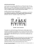
Transistors can be inserted bridging the center of the breadboard or with leads-in-line on one side of the socket. Diodes, resistors, and capacitors may be inserted in the same manner as jumper wires. BROKEN WIRES Sometimes a wire will break off at the surface of a breadboard contact hole. Two ways of solving this problem are as follows: 1. Push the broken wire into the socket. This will not affect the operation of the contact. 2.
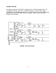
POWER SUPPLIES Each power supply of the PB-203A is regulated using a 7805 Integrated Circuit. This circuit provides the plus and minus 15 Volt rail voltages, as well as the 5V supply available for use in breadboard experiments. Resistors R4 and R6 are the programming potentiometers, which are factory-set for 15V outputs. Figure 2 shows the circuit diagram of the PB-203A. FIGURE 2.
USING THE PB-203A The PB-203A is ideally suited for virtually any type of bread-boarding circuitry, from TTL, CMOS and ECL, to op-amps, audio, comparators, video amps, microprocessor components, phase locks and more. In order to get the most out of your breadboarding experience, the following guidelines and tips should be observed.
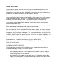
GND + -15V - 5V - 15V + +5V + 20V + +15V + 30V - - - -15V FIGURE 3.
SERVICE AND WARRANTY INFORMATION For up-to-date product information, please visit www.globalspecialties.com. For instructions on how to obtain a return merchandise authorization number (RMA), please visit our website, or call our customer service department. GLOBAL SPECIALTIES 22820 Savi Ranch Parkway Yorba Linda, CA 92887 800-572-1028 globalspecialties.com Global Specialties will service and repair this instrument free of charge for a period of 3 full years, subject to the warranty conditions below.