
Structural Report / Statische Berechnung F32


Büro für Tragwerksplanung und Ingenieurbau
vom Felde + Keppler
GmbH & Co. KG
Lütticher Straße 10
-
12
52064 Aachen
Telefon
:
0241 / 70 96 96
Telefax: 0241 / 70 96 46
b u er o @ v o m - fe l d e . de
INHALTSVERZEICHNIS
Table of contents
1 VORBEMERKUNGEN / GENERAL REMARKS ...............................................................................................1
1.1 Grundlagen / Basics ...................................................................................................................................1
1.2 Verwendete Baustoffe / Materials .............................................................................................................1
1.3 Allgemeine Beschreibung / General description .......................................................................................1
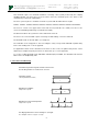
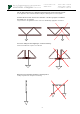
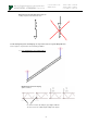
1.4 Geometrie und Belastung / Geometry and loading ....................................................................................2
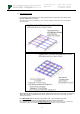
2 SYSTEM............................................................................................................................................................6
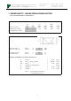
3 QUERSCHNITTS - UND MATERIALEIGENSCHAFTEN / SECTION- AND MATERIALPROPERTIES ........7
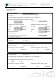
4 ZULÄSSIGE BELASTUNGEN EINZELBAUTEILE/ ALLOWABLE LOADING OF SINGLE COMPONENTS ..9
5 ZULÄSSIGE BELASTUNG EINFELDTRÄGER / ALLOWABLE LOADING SINGLE-SPAN GIRDER .......... 13
5.1 Gleichlast vertikal (UDL) / Uniformly distributed load (UDL) .................................................................. 13
5.2 Einzellast in Feldmitte (Single point load in ½ point): .............................................................................. 15
5.3 Einzellasten in den Drittelspunkten (Single point load in 1/3 point): ....................................................... 17
6 ZUSAMMENFASSUNG DER ERGEBNISSE / SUMMARY OF RESULTS ................................................... 19
6.1 Zulässige Belastung – Fall freihängende Traverse / Allowable loading – case free hanging truss: ....... 19
6.2 Vorhandene Durchbiegung unter max. Belastung – Fall frei hängende Traverse: ................................. 20
Deflections at max. allowable loadings - case free hanging truss
6.3 Zulässige Belastung und vorhandene Durchbiegung – Fall Installation als GRID:................................. 21
Allowable loadings and deflection – case installation as GRID
ANHÄNGE /
ANNEXES
. . . . . . . . . . . . . . . . . . . . . . . . . . . . . . . . . . . . . . . . . .
Zeichnungen Systeme F32. . . . . . . . . . . . . . . . . . . . . . . . . . . . . . .
Drawings F32
F32050-Model, F32100-Model, F32150-Model, F32200-Model,
F32250-Model, F32300-Model, F32350-Model, F32400-Model,
F32450-Model, F32500-Model