User’s Manual Mini-ITX-Motherboard-2807840 Version 5.
Copyrights This manual is copyrighted and all rights are reserved. It does not allow any non authorization in copied, photocopied, translated or reproduced to any electronic or machine readable form in whole or in part without prior written consent from the manufacturer.
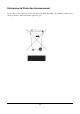
Environmental Protection Announcement Do not dispose this electronic device into the trash while discarding. To minimize pollution and ensure protection of the environment, please recycle.
USER’S NOTICE.....................................................................................................................ii MANUAL REVISION INFORMATION ..............................................................................ii ITEM CHECKLIST ................................................................................................................ii CHAPTER 1 INTRODUCTION OF VIA CN700 CHIPSET MOTHERBOARD 1-1 FEATURE OF MOTHERBOARD .........................................................
USER’S NOTICE COPYRIGHT OF THIS MANUAL BELONGS TO THE MANUFACTURER. NO PART OF THIS MANUAL, INCLUDING THE PRODUCTS AND SOFTWARE DESCRIBED IN IT MAY BE REPRODUCED, TRANSMITTED OR TRANSLATED INTO ANY LANGUAGE IN ANY FORM OR BY ANY MEANS WITHOUT WRITTEN PERMISSION OF THE MANUFACTURER. THIS MANUAL CONTAINS ALL INFORMATION REQUIRED TO USE THIS MOTHER-BOARD AND WE DO ASSURE THIS MANUAL MEETS USER’S REQUIREMENT BUT WILL CHANGE, CORRECT ANY TIME WITHOUT NOTICE.
Chapter 1 Introduction of VIA CN700 Chipset Motherboards 1-1 Feature of motherboard The VIA CN700 Chipset motherboard series are designed for the new generation VIA C7™ processor family guaranteed both of the performance and stability of general purpose IPC and dedicated IPC platform solutions.
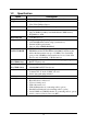
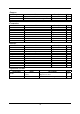
1-2 Specification Spec Design Chipset CPU Description ∗ ∗ ∗ ∗ Mini ITX form factor 6 layers PCB size: 17.0x17.
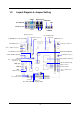
1-3 Layout Diagram & Jumper Setting COM1 PS/2 MOUSE Optional LAN LINE-OUT MIC PS/2 Keyboard VGA USB Parallel Connector ATX Power Connector USB/KB/MS Power ON Jumper(JP1) LINE-IN VIA C7 EBGA CPU CPU FAN SFAN1 DIMM Socket X1 Speaker/Power LED Conn.
Jumpers Jumper JP1 JP3 JBAT Name Keyboard Power ON Function Setting USB Power On Function Setting CMOS RAM Clear Function Setting Description 3-pin Block 3-pin Block 3-pin Block Page p.5 p.5 p.
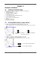
Chapter 2 Hardware installation 2-1 Hardware installation Steps Before using your computer, you had better complete the following steps: 1. Check motherboard jumper setting 2. Install CPU and Fan 3. Install System Memory (DIMM) 4. Install Expansion cards 5. Connect IDE and Front Panel /Back Panel cable 6. Connect ATX Power cable 7. Power-On and Load Standard Default 8. Reboot 9. Install Operating System 10.
(3) CMOS RAM Clear (3-pin): JBAT A battery must be used to retain the motherboard configuration in CMOS RAM short 1-2 pins of JPAT to store the CMOS data. To clear the CMOS, follow the procedure below: 1. Turn off the system and unplug the AC power 2. Remove ATX power cable from ATX power connector 3. Locate JBAT and short pins 2-3 for a few seconds 4. Return JBAT to its normal setting by shorting pins 1-2 5. Connect ATX power cable back to ATX power connector Note: When should clear CMOS 1.
CPU L2 Cache - The flash memory inside the CPU, normally Pentium III CPU has 256K or above, while Celeron CPU will have 128K. 2-3-1 Setting CPU Bus Clock & Memory Clock Jumper Setting the front side bus frequency and SDRAM frequency The motherboard uses jumper less function for the front side bus frequency and SDRAM frequency users don’t need setting any jumper when plug the CPU in motherboard For experience user looking for over clocking possibility, please refer to sec 2-3-2.
2-4 Install Memory The motherboards provide one 240-pin DUAL INLINE MEMORY MODULES (DIMM) sites for memory expansion available from minimum memory size of 64MB to maximum memory size of 1.0GB DDR2 SDRAM. Valid Memory Configurations Bank Bank 0, 1 (DDR1) Total 240-Pin DIMM DDR2 533/DDR2 400 DDR2 SDRAM Module System Memory (Max. 1.0GB) PCS Total Memory X1 64MB∼1.0GB 1 64MB∼1.
2-5 Expansion Cards WARNING! Turn off your power when adding or removing expansion cards or other system components. Failure to do so may cause severe damage to both your motherboard and expansion cards. 2-5-1 Procedure For Expansion Card Installation 1. 2. 3. 4. 5. 6. 7. Read the documentation for your expansion card and make any necessary hardware or software setting for your expansion card such as jumpers. Remove your computer’s cover and the bracket plate on the slot you intend to use.
2-6 Connectors, Headers 2-6-1 (1) Connectors Power Connector (24-pin block) : ATXPWR ATX Power Supply connector. This is a new defined 24-pins connector that usually comes with ATX case. The ATX Power Supply allows to use soft power on momentary switch that connect from the front panel switch to 2-pins Power On jumper pole on the motherboard.
(3) USB Port connector: UL1 / UL2 The connectors are 4-pins connector that connect USB devices to the system board, and standard RJ45 connector for Gigabit or 10/100 BASE-T LAN function. (4) Serial Port Connector (9-pin female): COM1 Serial Port connector is a 9-pin D-Subminiature connector. The On-board Serial Port can be disabled through the BIOS SETUP. Please refer to Chapter 3 “INTEGRATED PERIPHERALS SETUP” section for more detail information.
(8) Serial-ATA Port connector: SATA1 / SATA2 This connector supports the provided Serial ATA IDE hard disk cable to connecting the motherboard and serial ATA hard disk. 2-6-2 Headers (1) COM2 Serial Port Headers (9-pin) : COM2 This board has two serial port COM1 (Connector)/COM2(Headers), it come with cable providing serial port COM1/COM2. The On-board serial port can be disabled through BIOS SETUP. Please refer to Chapter 3 “INTEGRATED PERIPHERALS SETUP“ section for more detail information.
AUD-RET-L AUD-GND AUD-VCC AUD-RET-R AUDIO 2 10 Pin 1 AUD-MIC AUD-MIC-BIAS AUD-FPOUT-R HP-ON AUD-FPOUT-L 9 Line-Out, MIC Headers +DATA GND OC VCC -DATA VCC +DATA GND -DATA +DATA GND Pin 1 VCC Pin 1 USB2 -DATA +DATA GND OC -DATA USB1 VCC (4) USB Port Headers (9-pin) : USB1/USB2 These headers are used for connecting the additional USB port plug. By attaching an option USB cable, your can be provided with two additional USB plugs affixed to the back panel.
PWRBTN PWR LED PWRBTN GND GND RSTSW NC VCC5 PWRLED JW FP PWRLED SPEAK Pin 1 SPKR NC GND VCC5 RESET HDLED VCC5 HDDLE Pin 1 System Case Connections (10) FAN Speed Headers (3-pin) : CPUFAN, SFAN1/SFAN2 These connectors support cooling fans of 350mA (4.2 Watts) or less, depending on the fan manufacturer, the wire and plug may be different. The red wire should be positive, while the black should be ground. Connect the fan’s plug to the board taking into consideration the polarity of connector.
2-7 Starting Up Your Computer 1. After all connections are made, close your computer case cover. 2. Be sure all the switch are off, and check that the power supply input voltage is set to proper position, usually in-put voltage is 220V∼240V or 110V∼120V depending on your country’s voltage used. 3. Connect the power supply cord into the power supply located on the back of your system case according to your system user’s manual. 4. Turn on your peripheral as following order: a. Your monitor. b.
Any advice or comments about our products and service, or anything we can help you with please don’t hesitate to contact with us. We will do our best to support your products, projects and business. Address: Global American, Inc. 17 Hampshire Drive Hudson, NH 03051 Telephone: Toll Free (U.S. Only) 800-833-8999 (603)886-3900 FAX: (603)886-4545 Website: E-Mail: http://www.globalamericaninc.com salesinfo@globalamericaninc.