G4 Counter Top OPERATION MANUAL 1|Page
Table of Contents Introduction…….…………………………………………………………………………………3 Receiving………….…………………………………………………………………………….…..4 Description Model G3 & G4……………………………………………………………...5/6 Water Production Flow Chart….…………………………………………………………..7 Positioning the Cooler………………….……………………………………………………..8 Water Cooler Connections…………….…………………………………………………….9 Feed Water Connection……………….…………………………………………………....10 Drain Connection……………………….………………………………………………….….11 EZ Connections………………………….……………………………………………………...
Introduction Congratulations on your purchase of our revolutionary Bottle-less Water Cooler! Our coolers are all designed to replace the conventional 5-gallon water bottles while eliminating the hassles of deliveries, lifting bottles, and by eliminating plastic bottles from landfills. Our coolers are designed to produce pure, great tasting water for the whole family that is clean and safe to drink.
Receiving the Cooler Unpacking Global Water products are shipped completely assembled and ready to operate. Remove the top of the box and slide the water cooler out and save the box and packing materials. Inspection Inspect the cooler for shipping damage. Look at the exterior panels to see if they have been dented or damaged. Check the dispensing spigots in the front. Open the bottom panel to assure that the filter system is in tact.
Description Model G4 Counter Top Figure 2.
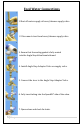
Water Production Flow Chart , Figure 3.
Positioning the Cooler It is not recommended to install this cooler in an area were water may cause severe or costly damage. 2) Do not position the cooler where it can be hit or bumped by vacuum cleaners or floor waxing machines. This can cause breaks in the waterline, connection fittings, and compressor tubing.
Water Cooler Connections When you receive the water cooler, the water connections on the back of the cooler have tube plugs in them. These tube sections must be removed before making all your connections. To remove the tube sections see Figure 7, “Disconnect”. The one-quarter inch plastic tubing should be used for making the Feed Water and Drain connections. If hard copper tubing is used for the Feed Water and Drain connections, the bulkhead fittings must be changed to a metal fitting. Figure 4.
Feed Water Connections 1.Shut off water supply at brass/chrome supply valve. 2. Disconnect riser from brass/chrome supply valve. 3. Ensure that the sealing gasket is fully seated into the Angle Stop Valve female thread. 4. Install Angle Stop Adapter Valve on supply valve. 5. Connect the riser to the Angle Stop Adapter Valve. 6. Fully insert tubing into the Speedfit® side of the valve. 7. Open valves and check for leaks.
Drain Connection The drain connection applies to models with Reverse Osmosis, “RO.” The black drain line in the back (Figure 4) must be hooked to the drain line ahead of the normal sink water trap. See Figure 5 below. Place the two-part drain saddle on the drain pipe before the drain trap. Allow proper space for the drilling operation. Tighten the saddle bolts evenly on both sides. Using the opening in the drain outlet saddle as a guide, drill a one-quarter inch (1/4) hole in the drain pipe.
EZ Connections The standard tubing connections on the water coolers are EZ connect fittings. Use tubing and follow the instructions below in Figure 7 to make the connections. If you cut the tubing, make sure it is a square cut, fits squarely in the fitting, and seals properly. Cut the tube square. “O” Ring Collet Stainless Steel Teeth Cut the tube square. It is essential that the outside diameter is free of score marks and that burrs and sharp edges be removed before inserting into fitting.
Start-Up Flush Open the right side panel to access filter assembly. Then, turn the water off at the ball valve on at the at the water connection. This brings water to the ball valve. Disconnect the tube from the second stage carbon filter (red circle in figure bellow), and place a cup or pan right underneath the hole to catch water. Open ball valve inside the cooler 1/4-turn. The handle in line with the tube is “on.” Let water flow through filters into the bucket or pan to push out air and carbon fines.
Tank Flush Flush tanks flush by draining all water through the drain plug located on the bottom of the cooler. The tanks drain water through the dispensing spigots. Fill and empty the tanks three times with the filtered water. This ensures great tasting water. When the tank has filled again with filtered water, the cooler is ready to dispense water. You may now turn on the Hot and Cold buttons on the back of the machine.
Cleaning and Maintenance Sanitize Fill the main water tank with water. Add one to two teaspoons of liquid chlorine bleach. Let stand for five to 10 minutes. Drain the water, then let water from filters refill tank and drain a second time. Remember to drain from dispensing spigots also. Note: Upon completion of cleaning, wait at least 10 minutes after the power cord is plugged in before turning on the Hot and Cold Water buttons.
Filter Replacement The filter elements must be replaced at regular intervals to maintain the quality of the water. The G4CTF have two stages of mechanical filtration. The first stage is the 5-micron sediment filter. The second stage is the activated carbon filter. The filter elements in all stages must be replaced every six months. The G4CTRO models have the two stages of filtration plus an additional Reverse Osmosis membrane filter. The three pre-filters must be replaced every six months.
Reverse Osmosis Membrane Replacement RO versions (RO) (every three years) a) Use the same procedure as above sec a-c. b) Remove the RO stage from the clips. Disconnect the white tubing from the RO housing cap. c) Remove the cap from the housing by unscrewing it. d) Using a pair of pliers, remove the RO element from the housing by grasping the tube end and pulling it out. e) Use RO filter replacement P/N 50GPD (50gpd CSM membrane).
Trouble Shooting Guide PROBLEM No Power CAUSE No electric current flowing. Cold Water not cold enough The cooler is placed too close to the wall. Wire Condenser on backside is dusty. Compressor does not have enough refrigerant. Hot Water doesn’t flow out of spigot Air may be trapped in the line. Won’t cool Controls not set. Panel not lit No power. No hot water at start up Hot tank overheat protection sensor tripped. SOLUTION Make sure the cooler is plugged in and check for improper connections.
Specifications Model No. G4CT Voltage/Frequency AC110V Dimensions (L)18 (W)11 (H)16 Weight (empty) 42lb. Hot Water Tank Capacity .5 gal. Cold Water tank Capacity .5 gal. Power Consumption Hot Water: 500W Cold Water: 100W Electric Power Cord Length 18 | P a g e 6Ft.
Warranty All Global Water products are warranted to be free from defects in materials and workmanship under normal use within the condition of operation listed for a period of one year from the date of purchase. The compressor has a 3-year warranty. There is no liability assumed by the company for damage due to water leakage or other secondary effects from any component defect. Labor is not covered in this warranty. The warranty applies when “Conditions of Operation” below are met.
Tel. (866) 289-7518 Fax (786) 207-2570 E-mail GlobalWaterFlorida@Gmail.com Cleaner, Healthier Water www.GlobalWaterInc.