GLOBALSAT GPS Engine Board Hardware Data Sheet Product No : ET-314AC Version 2.2 Globalsat Technology Corporation 16F., No. 186, Jian-Yi Road, Chung-Ho City, Taipei Hsien 235, Taiwan Tel: 886-2-8226-3799 Fax: 886-2-8226-3899 E-mail : service@globalsat.com.tw Website: www.globalsat.com.
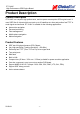
ET-314AC High Performance GPS Engine Board Product Description Product Description ET-314AC is a compact, high performance, and low power consumption GPS engine board. It uses SiRF Star III chipset which can track up to 20 satellites at a time and perform fast TTFF in weak signal environments.
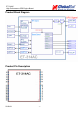
ET-314AC High Performance GPS Engine Board Product Block Diagram Product Pin Description 2010/4/1 -3-
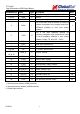
ET-314AC High Performance GPS Engine Board PIN Number(s) Name Type Description Note 1 VCC P Main power supply to the engine board. 2,10,30 GND P Ground. 3 BOOTSEL I Set this pin to high for programming flash. 2 I This is the main receive channel for receiving software commands to the engine board from SiRFdemo software or from user written software.
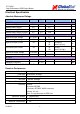
ET-314AC High Performance GPS Engine Board Electrical Specification Absolute Maximums Ratings Parameter Min. Typ. Max. Conditions Unit Main power supply 3.1 3.3 3.5 V Backup battery supply 2.0 3.5 V POWER Supply Main power supply Current 26.70 mA Backup battery supply Current 4.5 5.0 12.6 Interface (VCC = 3.3V, VBAT= 3.3V, Operation Temp.= 25℃) uA High Level input Voltage 0.7*VDD 3.5 V Low Level input Voltage -0.3 0.3*VDD V High Level input Current -10 10 60 (V=2.
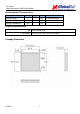
ET-314AC High Performance GPS Engine Board Environmental Characteristics Parameter Min Humidity Range Typ 5 Operation Temperature -40 Storage Temperature -40 Max 95 25 Unit 85 % non-condensing ℃ 85 ℃ Physical Characteristic Type 30-pin stamp holes Dimensions 25.4 mm *25.4 mm * 2.50 mm ±0.
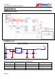
ET-314AC High Performance GPS Engine Board Application Application Circuit POWER Circuit GPS POWER VIN C1 22UF/10V 1 2 3 U1 VIN VOUT GND CE NC L1 5 4 XC6209B332MRN 3.3V GPS_3V3 BLM18AG121SN1D C2 C3 10UF/16V 470PF GPS Active Antenna Specifications (Recommendation) Frequency: 1575.42 + 2MHz Amplifier Gain: 18~22dB Typical Axial Ratio: 3 dB Typical Output VSWR: 2.0 Max. Output Impedance: 50Ω Noise Figure: 2.0 dB Max Polarization: Antenna Input Voltage: 2.85V (Typ.
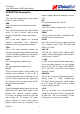
ET-314AC High Performance GPS Engine Board OPERATING Description battery voltage should be between 2.0V and 3.5V. VCC This is the main power supply to the engine board. (3.1Vdc to 3.5Vdc) NC ET-314AC reserves PIN, Just NC. GND This is Ground pin for the baseband circuit. VDD28OUT This PIN is output voltage 2.85V. If do not use it, Just NC. GND_A This is Ground pin for the ET-314AC RFand circuit. To use ET-314AC, GND_A need connect to GND with L bead or 0Ω resistor. RESET This pin is input low active.
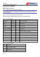
ET-314AC High Performance GPS Engine Board SOFTWARE COMMAND NMEA Output Command GGA - Global Positioning System Fixed Data Note – Fields marked in italic red apply only to NMEA version 2.3 (and later) in this NMEA message description Table A-1 contains the values for the following example: $GPGGA,161229.487,3723.2475,N,12158.3416,W,1,07,1.0,9.0,M,,,,0000*18 Table A-1 GGA Data Format Name Example Units Description Message ID $GPGGA GGA protocol header UTC Time 161229.487 hhmmss.sss Latitude 3723.
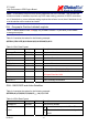
ET-314AC High Performance GPS Engine Board Note – A valid status is derived from all the parameters set in the software. This includes the minimum number of satellites required, any DOP mask setting, presence of DGPS corrections, etc. If the default or current software setting requires that a factor is met, then if that factor is not met the solution will be marked as invalid. GLL - Geographic Position-Latitude/Longitude Note – Fields marked in italic red apply only to NMEA version 2.
ET-314AC High Performance GPS Engine Board 1 Fix Not Available Mode 2 3 2 2D 3 3D Satellite Used 1 07 Sv on Channel 1 Satellite Used 1 02 Sv on Channel 2 ….. Satellite Used1 Sv on Channel 12 2 1.8 Position dilution of Precision 2 HDOP 1.0 Horizontal dilution of Precision VDOP2 1.5 Vertical dilution of Precision Checksum *33 PDOP 1. 2. End of message termination Satellite used in solution. Maximum DOP value reported is 50.
ET-314AC High Performance GPS Engine Board SNR(C/No) 42 Checksum *71 dBHz 1. Range 0 to 99,null when not tracking End of message termination Depending on the number of satellites tracked, multiple messages of GSV data may be required. In some software versions, the maximum number of satellites reported as visible is limited to 12, even though more may be visible. RMC - Recommended Minimum Specific GNSS Data Note – Fields marked in italic red apply only to NMEA version 2.
ET-314AC High Performance GPS Engine Board are geodetic WGS84 directions relative to true North. VTG - Course Over Ground and Ground Speed Note – Fields marked in italic red apply only to NMEA version 2.3 (and later) in this NMEA message description Table A-7 contains the values for the following example: $GPVTG,309.62,T,,M,0.13,N,0.2,K,A*23 Table A-7 RMC Data Format Name Example Message ID $GPVTG Course 309.
ET-314AC High Performance GPS Engine Board NMEA Input Command A). Set Serial Port ID: 100 Set PORTA parameters and protocol This command message is used to set the protocol (SiRF Binary or NMEA) and/or the communication parameters (baud rate, data bits, stop bits, and parity). Generally, this command is used to switch the module back to SiRF Binary protocol mode where a more extensive command message set is available.
ET-314AC High Performance GPS Engine Board B). Navigation lnitialization ID:101 Parameters required for start This command is used to cause a restart of the receiver, and to specify the type of restart. Optionally, it may also initialize position (in X, Y, Z ECEF coordinates), clock drift, GPS Time Of Week and GPS Week Number. This enables the receiver to search for the correct satellite signals at the correct signal parameters.
ET-314AC High Performance GPS Engine Board Table B-3 Reset Configuration Bit Map Bit Description 0☆ Data valid flag: 1 = Use data in ECEF X, Y, Z, Clock Offset, Time of Week and Week number to initialize the receiver; 0 = Ignore data fields 1 Clear ephemeris from memory: blocks Snap or Hot Start from occurring 2 Clear all history (except clock drift) from memory: blocks Snap, Hot, and Warm Starts 3 4 Factory Reset: clears all GPS memory including clock drift.
ET-314AC High Performance GPS Engine Board C). Set DGPS Port ID: 102 Set PORT B parameters for DGPS input This command is used to control the serial port used to receive RTCM differential corrections. Differential receivers may output corrections using different communication parameters. If a DGPS receiver is used that has different communication parameters, use this command to allow the receiver to correctly decode the data.
ET-314AC High Performance GPS Engine Board Mode 01 Rate 00 CksumEnable 01 .
ET-314AC High Performance GPS Engine Board Table B-8 LLA Navigation Initialization Data Format Name Example Unit Description Message ID $PSRF104 Lat 37.3875111 degrees Latitude + = North (Range 90 to -90) Lon -121.
ET-314AC High Performance GPS Engine Board F). Development Data On/Off ID: 105 Switch Development Data Messages On/Off This command turns development data (debug messages) on and off. Development data can be used to help diagnose system problems since many parts of the software contain messages that are output when problems are detected.
ET-314AC High Performance GPS Engine Board PCB Layout Recommend Recommended Layout PAD Unit: mm Tolerance: 0.1mm PCB Layout Recommendations Do not routing the other signal or power trace under the engine board. RF: This pin receives signal of GPS analog via external active antenna .It has to be a controlled impedance trace at 50ohm. Do not place the RF traces close to the other signal path and not routing it on the top layer. Keep the RF traces as short as possible.
ET-314AC High Performance GPS Engine Board Recommended Reflow Profile: Pre heating temperature: Heating temperature: 2010/4/1 150±10[℃] 235±5[℃] Pre heating time: Heating time: - 22 - 90±30[sec.] 10±1[sec.