AVL Tracking System TR-606B GlobalSat WorldCom Corporation st 16F., No. 186, Jian 1 Rd, Zhonghe Dist., USGlobalSat Incorporated New Taipei City 23553, Taiwan 14740 Yorba Court Chino, CA 91710 Tel: 886.2.8226.3799/ Fax: 886.2.8226.3899 service@globalsat.com.tw www.globalsat.com.tw Tel: 888.323.8720 / Fax: 909.597.8532 sales@usglobalsat.com www.usglobalsat.
CONTENT 1. Introduction ....................................................................................................................................... 3 1.1 Introduction ............................................................................................................................. 3 1.2 Features .................................................................................................................................... 3 1.3 Hardware Architecture ...............................
1. Introduction 1.1 Introduction The TR-606B is a multi-functional and economically feasible communication platform for mobile positioning applications. It integrates highly sensitive GPS module, dual-band UMTS/HSDPA and quad-band GSM communication module with a powerful microcontroller that fits into a compact enclosure. The TR-606B has a solid and rigid housing, for simple installation.
1.
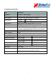
1.4 Hardware specification Item Description Dimension 98 mm X 71 mm X 22 mm CPU High performance line ARM-base 32-bit MCU GPS receiver SiRF Star III high performance GPS chipset Temperature Operation -30℃ ~ + 80℃ Storage -40℃ ~ + 85℃ GPS Antenna SMA Type connector. Active antenna ( 3.3~3.8V) GSM Antenna SMA Type connector.
1.
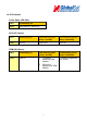
1.6 LED indicator Power Status LED (Red) LED Permanently On State Main power on, device on GPS LED (Yellow) LED Permanently off Fast blinking (Once every 1 second) Slow blinking (Once every 3 seconds) State GPS off GPS not fix GPS fix GSM LED (Green) LED Permanently off Fast blinking (Once every 1 second) Slow blinking (Once every 3 seconds) State GSM off 1. TR-606B is registered full service 2.
1.
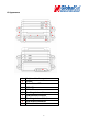
8 Pin Cable Wire Color Description Pink Audio_5V Blue Speaker 1(Positive) Red Serial-1_5V White Receiver 1 White Microphone 1 P Black (3 Pieces) Ground Orange Speaker 1(Negative) Green Transmission 1 9
1.
2 Operation For first time users, please follow the steps below to complete the pre-installation. 2.1 Install the SIM card With the cooper contacts face-up, align the notch on the SIM card with the notch on the SIM slot and insert the SIM card. If SIM is inserted correctly, you will not be able to see the copper contacts after inserting the card. To eject SIM card, simply, use your finger nail and apply slight pressure.
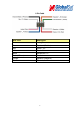
2.2 Install the GPS and GSM antenna Install the GSM antenna to the GSM antenna port on the left side of the back of the device and install the GPS antenna to the GPS antenna port on the right side of the back of the device making sure both antennas tightly screwed in place. Please refer to the photo above.
2.3 Installing the Emergency button There is a line of the 14 pin IO cable for connecting push button for emergency help. One end of the button must be connected to the emergency line and the other end must be connected to the ground line.