User Manual Models Included: SmartOneA, SmartOneB, SmartOneBLP Revision: 1.
Table of Contents Addendum..................................................4 SMARTONE Basics...........................................5 Overview..................................................5 Modes of Operation......................................5 Standard Messaging......................................5 Reduced Messaging.......................................6 Theft Recovery..........................................6 Inputs....................................................7 Serial Commands.......
Change of Location Area Tab .......................... 40 Inside Change of Location Area Section ............... 39 Outside Change of Location Area ...................... 42 Input Settings Tab ................................... 42 Options Tab .......................................... 44 Messages................................................. 45 Basic User Information ................................. 45 Global Message Type .................................. 45 Type 0 Message Class ......................
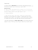
Addendum I. A new version, SmartOne LP, is available. This version can be powered by line power or batteries. It can be supplied line power with the External Inputs Cable or the Serial Input Cable. Specifications: A. Input Voltage- The SmartOne LP will operate on 10 to 48 Volts DC. B. Switching- If batteries are installed, the unit will automatically switch to battery power if line power input is lost. C. Connection Method- 1.
SMARTONE Basics Overview The SMARTONE is designed to track the position of Trailers, Cargo Containers, Heavy Construction Equipment, Generators, Boats/Barges and any other mobile assets. The SMARTONE also has 2 inputs to manage run time of engines and/or other alarm inputs. The SMARTONE processes GPS satellite signals to obtain its position in terms of longitude and latitude and transmits this information over Globalstar’s Simplex Satellite Network.
Usage Example: A Company is required to report the GPS locations of their hazardous chemical containers twice a day. Based on this requirement the Company has 2 options: set a message interval of every 12 hours, the 12 hour internal begins when the device is powered up or configure message times of day 12:00 noon and 12:00 midnight.
Once the SMARTONE’s position is outside of the Change of Location Area, it alerts the SMARTONE to an unauthorized movement and immediately sends a location message (Change of Location Alert Message). The SMARTONE then continues to send location messages at a message interval set during the configuration process until the power is turned off or the battery is dead.
The SMARTONE also allows the user to define the Message Interval while the Inputs are in an Undesired State, either Opened or Closed. Usage Example: A company has remote containers at job sites and would like to know if a door is ajar. If a door is left ajar the company would like a notification every 2 hours. Based on this requirement, the SMARTONE would be connected to an open door sensor with the Undesired Input State Message enabled and set as Opened with a Message Interval of 2 hours.
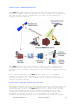
Satellite Communications The SMARTONE communicates with both the GPS satellite Network and the Globalstar Simplex Satellite Network. All GPS locations are pulled from the GPS network and all transmissions are sent via the Globalstar Simplex Satellite Network. The SMARTONE has the unique ability to check its GPS Coordinates at a programmable rate while it is inside of the Change of Location Area without actually sending a message over the Globalstar Simplex Satellite Network.
where the mobile device must be pointed toward a specific direction in the sky. Geostationary satellites also orbit at a much higher altitude and move along the equator. Messages are transmitted from the SMARTONE via the Globalstar Simplex Satellite Network using an uplink-only connection (one-way data transmission) and received by a Globalstar Simplex Ground Station.
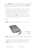
Battery Placement Turning On and Off To turn the device ‘On’ or ‘Off’, remove the connector cover from the end of the device. Then invert and replace the connector cover so that the word ‘Off’ or ‘On’, whichever is desired is visible. *See Appendix F – Battery Installation Guide for further information on how the connector cover should engage with the SMARTONE. SmartOne Manual Rev 1.4 DOC# 9100-0268-01 p.
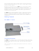
Mounting The SMARTONE is designed to be mounted to an asset using double-sided adhesive tape and/or the included mounting bracket. The mounting bracket has four screws that attach to the asset and allows the SMARTONE to be mounted so the antenna can face the sky whether mounted internally or externally. This enables the antenna to have a direct view of the sky with mounting flexibility. The SMARTONE attaches to the mounting bracket using four Phillips-head screws.
Connecting Devices The SMARTONE, with batteries installed and battery cover screwed down, connects to a PC using a USB Configuration Cable. The SMARTONE Configuration Software may be used without being connected to devices to prepare configurations, but must be connected to a device using the USB Configuration Cable to Program. Once the Program button has been depressed the Configuration Cable should not be disconnected, if already connected, from the device and/or the computer.
User Data Entry Pane The user data entry pane contains a context-switched user entry area for displaying and inputting configuration data. The information is organized in pages with page manipulation provided through tabs along the top of the pane. Selecting a tab will change the context of the upper pane. The tabs are named to group similar functions on the same page. The tabs will change according to the operation Mode selected.
View Summary Button This button causes the Configuration Software to open a separate window, which contains plain text readout of every user configurable parameter that exists for the SMARTONE. View Summary Window The Menu Bar in the View Summary Window allows the user to either print the parameters or save the configuration parameters to a text file. This window remains open while the user manipulates the fields in the User Data Entry Pane tabs and will update as changes are made. SmartOne Manual Rev 1.
Program Button The PROGRAM button in the Status Pane is used to send the data in the Configuration Software to the connected SMARTONE (s). The SMARTONE will be updated with the data from the Configuration Software. The user is queried to confirm device program before execution of the function. File Menu in the View Summary Window allows the user to either save the configuration to file or print configuration. Toolbar File Menu New Configuration.
Save Configuration. This will open a window that allows the user to browse to a location and save all of the configuration settings to two separate files: The configuration file. This file is non-editable. A text file. An ASCII format file that contains each parameter and parameter value in a standard delimited format. Open Configuration from History. Every time a device is successfully programmed, the configuration will save that occurrence to a text log file.
Send Location Message - causes the SMARTONE connected to the COM port to obtain a GPS fix and send a Location Message. Send Diagnostic Message – causes the SMARTONE connected to send diagnostic information including battery status, GPS average search time, GPS fails and number of transmissions since last diagnostic message. Send Data w/GPS Message - causes the SMARTONE to seek a GPS location, and then send a Truncated SMARTONE message (type 1).
There are two menu options available in the pop up window: Print Diagnostic –prints the diagnostic information. Save Text to File – Opens a window, which allows the user to browse for a location and save the diagnostic information in a text file. Test Vibration Sensor Button is used to find the minimum, maximum and average vibration sensitivity detected by the sensor. This information helps to determine the appropriate Level of Sensitivity for the vibration sensor.
Help Menu About. This pops up a window with the SMARTONE Configuration version number. Getting Started Tab The Getting Started Tab allows the user to select the Mode of operation for the SMARTONE. The Modes include Standard Messaging with or without motion, Reduced Messaging and Theft Recovery Mode. SmartOne Manual Rev 1.4 DOC# 9100-0268-01 p.
Standard Messaging Mode without Motion The Standard Messaging without Motion Mode is selected for basic tracking functionality on the SMARTONE. The SMARTONE will automatically report its position at regular time intervals. The messages sent in this Mode are called Location Messages. These messages include the GPS coordinates of the actual location of the SMARTONE. In this Mode, the vibration sensor is OFF. SmartOne Manual Rev 1.4 DOC# 9100-0268-01 p.
Standard Messaging Mode with Motion The Standard Messaging with Motion Mode is selected for basic tracking functionality with motion detection capabilities. The user defines the motion parameters for each application including the Level of Sensitivity of the vibration sensor, Time to be in a State of Vibration and Time to be in a State of Lacking Vibration. The SMARTONE can be set to report at a different rate, Message Interval while In Motion, compared to the Location Message Interval.
Standard Messaging Mode without Motion Location Messages Tab Message Interval. The SMARTONE can be configured to report at a specific message interval specified by days, hours and minutes. The SMARTONE accepts a single interval only. Once the interval has been entered in Days, Hours, and Minutes, click the ADD button to accept the interval and add it to the message interval box. Message – Time(s) of Day. The SMARTONE can be configured to report at specific time(s) of day.
The REMOVE button deletes the selected time of day or interval from the message interval box. The CLEAR button deletes all the time of days or interval in the message interval box. SmartOne Manual Rev 1.4 DOC# 9100-0268-01 p.
Input Settings Tab Status Changed Message. The SMARTONE has two inputs that can be configured to send a Status Changed Message once the selected input opens, closes, or in both events. The Message sent can or cannot contain the GPS coordinates of the device at the time the status of the input(s) changed. Undesired State Message. The SMARTONE can be configured to send messages throughout the time the input is in the desired state, either to opened or closed position.
the times in the Location Message Tab. SmartOne Manual Rev 1.4 DOC# 9100-0268-01 p.
Options Tab Device Turned On Message. The SMARTONE can be configured to send or not send a Device Turned On Message on Power-up. The default is enabled. Interval for Replace Battery Message. The SMARTONE can be configured to transmit a Replace Battery message based on a low battery condition. Configuration range extends from 0 to 45 days in steps of a day. The default is 1 day. The SMARTONE will detect low battery conditions while at least 100 more messages can still be transmitted.
Standard Messaging Mode with Motion Motion Settings Tab The Motion Settings Tab of the Configuration Software is used to define the Message Interval while In Motion. This tab also contains the Vibration Sensor Settings, which define how the sensitivity of the Vibration Sensor and how it determines the device is In Motion. Message Interval while In Motion.
Level of Sensitivity for Vibration Sensor. The vibration sensor has a range of sensitivity from 1 to 31 (1 being most sensitive and 31 being least sensitive). The smaller the sensitivity level, the more sensitive the vibration sensor would be to movement. Time to be in a State of Vibration. Time the vibration sensor must be above the sensitivity level before being in a State of Vibration.
Message Interval. The SMARTONE can be configured to report at a specific message interval specified by days, hours and minutes. The SMARTONE accepts a single interval only. Once the interval has been entered in Days, Hours, and Minutes, the ADD button will accept the interval and add it to the message interval box. Message – Time(s) of Day. The SMARTONE can be configured to report at specific time (s) of day. The message interval box allows up to 12 times of day to send Location Messages.
Status Changed Message. The SMARTONE has two inputs that can be configured to send a Status Changed Message once the selected input opens, closes, or in both events. The Message sent can or cannot contain the GPS coordinates of the device at the time the status of the input (s) changed. The SMARTONE can also send this message when it enters or exits the Vibration State. Undesired State Message.
Options Tab Device Turned On Message. The SMARTONE can be configured to send or not send a Device Turned On Message on Power-up. The default is enabled. SmartOne Manual Rev 1.4 DOC# 9100-0268-01 p.
Interval for Replace Battery Message. The SMARTONE can be configured to transmit a Replace Battery message based on a low battery condition. Configuration range extends from 0 to 45 days in steps of a day. The default is 1 day. The SMARTONE will detect low battery conditions while at least 100 more messages can still be transmitted. Interval for Diagnostic Message. The SMARTONE can send a diagnostic message with information on the diagnostic status of the device.
Inside Change of Location Area The parameters in this section define the functionality of the device while inside its Change of Location Area while in Reduced Messaging Mode. Change of Location Range. Change of Location Range specifies the length (in meters, kilometers, yards, or miles) from the center of the Change of Location Area. Message Interval inside the Change of Location Area. The SMARTONE can be configured to transmit messages while inside the Change of Location Area.
Level of Sensitivity for Vibration Sensor. The vibration sensor has a range of sensitivity from 1 to 31 (1 being most sensitive and 31 being least sensitive). The smaller the sensitivity level, the more sensitive the vibration sensor would be to movement. Time to be in a State of Vibration. Time the vibration sensor must be above the sensitivity level before being in a State of Vibration.
Change of Location Alert Message. The SMARTONE can be configured to send Change of Location Area Alert messages when the device leaves the Change of Location Area. This special message can be processed by the back office application to send a notification to a cellular phone or to an email account that the asset has left the Change of Location Area. The number of Change of Location Area Alert messages sent by the device is configurable with range from 0 to 3.
Input Settings Tab Status Changed Message. The SMARTONE has two inputs that can be configured to send a Status Changed Message once the selected input opens, closes, or in both events. The Message sent can or can not contain the GPS coordinates of the device at the time the status of the input (s) changed. The SMARTONE can also send this message when it enters or exits the Vibration State. Undesired State Message.
messages throughout the time the device is in the State of Vibration. Accumulate/Count Message: The SMARTONE can accumulate hours and events while input 1 or input 2 is enabled. The SMARTONE can send an accumulate/count message once the configurable number of hours or events have been reached. In addition, The SMARTONE can send the actual value of accumulated hours and events at configurable intervals specified in days, hours, and minutes. Options Tab Device Turned On Message.
message with information on the diagnostic status of the device. The diagnostic message includes battery status, GPS average search time, GPS fails and number of transmissions since last diagnostic message. Transmit interval of diagnostic messages with a transmission rate from 1 to 45 days. The default is 30 days. SmartOne Manual Rev 1.4 DOC# 9100-0268-01 p.
Theft Recovery Mode Change of Location Area Tab Inside Change of Location Area Section The parameters in this section define the functionality of the device while inside its Change of Location Area while in Theft Recovery Mode. Change of Location Range. Change of Location Range specifies the length (in meters, kilometers, yards, or miles) from the center of the Change of Location Area.
Message Interval inside the Change of Location Area. The SMARTONE can be configured to transmit messages while inside its Change of Location Area. This parameter allows you to configure the message interval inside the Change of Location Area in days, hours and minutes. In Theft Recovery Mode, the asset will send infrequent messages, user configurable interval, if asset is in its Change of Location Area. Position Check Interval while in State of Vibration.
Time to be in a State of Lacking Vibration. Time the vibration sensor must be below the sensitivity level before in a State of Lacking Vibration. Outside Change of Location Area The parameters in this section define the functionality of the device while outside its Change of Location Area. Change of Location Alert Messages. The SMARTONE can be configured to send Change of Location Area Alert messages when the device leaves the Change of Location Area.
Input Settings Tab Status Changed Message. The SMARTONE has two inputs that can be configured to send a Status Changed Message once the selected input opens, closes, or in both events. The Message sent can or can not contain the GPS coordinates of the device at the time the status of the input (s) changed. The SMARTONE can also send this message when it enters or exits the Vibration State. Undesired State Message.
have been reached. In addition, The SMARTONE can send the actual value of accumulated hours and events at configurable intervals specified in days, hours, and minutes. Options Tab Device Turned On Message. The SMARTONE is configured to send a Device Turned On Message on Power-up. The default is enabled. Interval for Replace Battery Message. The SMARTONE can be configured to transmit a Replace Battery message based on a low battery condition. Configuration range extends from 0 to 45 days in steps of a day.
Transmit interval of diagnostic messages with a transmission rate from 1 to 45 days. The default is 30 days. Messages The SMARTONE produces on-air messages conforming to the Globalstar specified format. The data being communicated to the end user is contained entirely in the 72 bit (9 byte) field. This section will describe the use of the 9 byte user information segment for communicating the range of information that the SMARTONE is able to convey to the user.
Type 0 Message Class Message Format Table 1 below shows the format of all standard messages. Specific variants of the message will be shown individually in following subsections. Byte Number 0 0 Variable Bits Type field 2 Battery state 1 GPS Data Valid 1 Missed Input State Change 2 GPS fail counter 2 Latitude/Longitude 48 Input Status 4 0 0 0 1,2,3,4,5,6 7 SmartOne Manual Rev 1.4 Description Bit (1:0) = 0 = message type: Bit (2) 0 = Good battery. 1 = replace battery.
7 8 8 Message Sub-Type 4 RESERVED 3 Vibration triggered message 1 Vibration bit. 1 2D 1 Motion 1 Fix Confidence Bit. 1 8 8 8 8 Bit 1: Input 1 state: 0 = Closed, 1 = Open Bit 2: Input 2 change: 0 = Did not trigger message, 1 = Triggered message Bit 3: Input 2 state: 0 = Closed, 1 = Open Bits (7:4) message sub-type code. See subtypes below.
Byte Number 0 0 Variable Bits Type field 2 Battery state 1 GPS Data Valid 1 Missed Input State Change 2 GPS fail counter 2 Latitude/Longitude 48 Input Status 4 Standard Message Sub-Type 4 0 0 0 1,2,3,4,5,6 7 7 SmartOne Manual Rev 1.4 Description Bit (1:0) = 0 = standard message type Bit (2) 0 = Good battery. 1 = replace battery. Bit (3) 0 = GPS Data valid in this message. 1 = GPS failed in this message cycle, ignore Latitude and Longitude fields. Bit (4) Missed Input 1.
8 8 RESERVED 3 Vibration triggered message 1 Vibration bit. 1 2D 1 Motion 1 Fix Confidence Bit. 1 8 8 8 8 Bits (2:0) RESERVED in SmartOne Bit (3) – Value 1 = This message is being sent because transmit on change of vibration state is selected and the vibration just changed state, or Undesired Vibration state is selected and the vibration is in the undesired state. Value 0 = This message is being transmitted for a reason other than the above reasons.
priority message. 0 GPS fail counter 2 Latitude/Longitude 48 Input Status 4 Standard Message Sub-Type 4 RESERVED 3 Vibration triggered message 1 Vibration bit. 1 2D 1 1,2,3,4,5,6 7 7 8 8 8 8 SmartOne Manual Rev 1.4 Bit (7:6) = GPS fail counter. Counts up to a maximum value of 3 upon GPS failure.
8 8 Motion 1 Fix Confidence Bit. 1 reported is from a 3D fix. Bit (6) – Value 1 = Device was In-Motion when the message was transmitted. Value 0 = Device was At-Rest when the message was transmitted. Bit (7) 0=High confidence in GPS fix accuracy, 1=Reduced confidence in GPS fix accuracy. Table 3 - Device Turned On message Change of Location Area Alert Message This is the message transmitted when the SMARTONE detects that it has left its Change of Location Area.
7 Input Status 4 Standard Message Sub-Type 4 RESERVED 3 Vibration triggered message 1 Vibration bit. 1 2D 1 Motion 1 Fix Confidence Bit. 1 7 8 8 8 8 8 8 360 degrees of Longitude coded in signed binary with 3 bytes and 180 degrees of Latitude coded in signed binary with 3 bytes.
Input Status Changed Message This is the message that will be transmitted upon the change of state of the inputs if enabled and as selected by the user Input 1 open, input 1 closed, input 1 both, input 2 open, input 2 closed, input 2 both. The Message Sub Type is 3. The Input status value of byte 7 in the message indicates which input changed state to trigger the message and also reports the states of both inputs. The message format is shown in table 5.
7 8 8 Standard Message Sub-Type 4 RESERVED 3 Vibration triggered message 1 Vibration bit. 1 2D 1 Motion 1 Fix Confidence Bit. 1 8 8 8 8 Bit 0: Input 1 change: 0 = Did not trigger message, 1 = Triggered message. Bit 1: Input 1 state: 0 = Closed, 1 = Open Bit 2: Input 2 change: 0 = Did not trigger message, 1 = Triggered message Bit 3: Input 2 state: 0 = Closed, 1 = Open Bits (7:4) Standard message sub-type code. Value is 3 in the Input Status Changed message.
the undesired state and triggering the Undesired Input State report rate. The message format is shown in table 6. Byte Number 0 0 Variable Bits Type field 2 Battery state 1 GPS Data Valid 1 Missed Input State Change 2 GPS fail counter 2 Latitude/Longitude 48 Input Status 4 Standard Message Sub-Type 4 0 0 0 1,2,3,4,5,6 7 7 SmartOne Manual Rev 1.4 Description Bit (1:0) = 0 = Standard message type: Bit (2) 0 = Good battery. 1 = replace battery.
8 8 RESERVED 3 Vibration triggered message 1 Vibration bit. 1 2D 1 Motion 1 Fix Confidence Bit. 1 8 8 8 8 the undesired input state message. Bits (2:0) RESERVED in SmartOne Bit (3) – Value 1 = This message is being sent because transmit on change of vibration state is selected and the vibration just changed state, or Undesired Vibration state is selected and the vibration is in the undesired state. Value 0 = This message is being transmitted for a reason other than the above reasons.
Input 2 was missed due to the transmission of a higher priority message. 0 GPS fail counter 2 Latitude/Longitude 48 Input Status 4 Standard Message Sub-Type 4 RESERVED 3 Vibration triggered message 1 Vibration bit. 1 2D 1 1,2,3,4,5,6 7 7 8 8 8 8 SmartOne Manual Rev 1.4 Bit (7:6) = GPS fail counter. Counts up to a maximum value of 3 upon GPS failure.
8 8 Motion 1 Fix Confidence Bit. 1 the fix.) Value 0 = GPS data reported is from a 3D fix. Bit (6) – Value 1 = Device was In-Motion when the message was transmitted. Value 0 = Device was At-Rest when the message was transmitted. Bit (7) 0=High confidence in GPS fix accuracy, 1=Reduced confidence in GPS fix accuracy. Table 7 - Re-center Message Type 1 Message Class Truncated message type – Single Packet Version (Supported in firmware version 2.0 and later.
presented to the user by the Globalstar back office as complete messages of a length longer than 9 bytes. The SmartOne supports user-defined messages (Class 1 and 2) of up to 54 bytes. This message type provides for up to 47 bytes plus 6 bits of user data to be appended to the status byte and GPS location information. The input and status bits data of the standard message are replaced with user data from the serial configuration port.
Byte 5 = User data byte 5 Byte 6 = User data byte 6 Byte 7 = User data byte 7 Byte 8 = User data byte 8 Raw message type – Multiple Packet Version (Supported in firmware version 2.1 and later.) The Globalstar simplex messaging protocol provides for single and multiple packet messaging. In the event that the user application requests a user data length exceeding 9 bytes, the SmartOne (running firmware version 2.
Type 3 Message Class The SMARTONE will use the Type 3 message class for the following message types: Diagnostic Message – Subtype 21. Replace Battery Message – Subtype 22. Contact Service Provider Message – Subtype 23. • Accumulate / Count Message – Subtype 24. Subtypes 0 – 3 are used by earlier tracker products. Diagnostic Message The Diagnostic Message includes battery status, GPS average acquisition time, GPS fails and number of transmissions since the last Diagnostic Message.
Replace Battery Message The Replace Battery message has a format almost identical to the Diagnostic message. If enabled by the user, the Replace Battery message will be sent by the SMARTONE when the battery charge level is at or below the replace battery advisement level. The message will be repeated at an interval configurable by the user for as long as the battery remains below the advisement level.
Contact Service Provider message unless the fault is determined to have cleared, and then determined to have come back again. The Contact Service Provider message is shown in table 10. Byte Number 0 0 1 1 1 1 1 Variable Bits Type Field 2 Subtype 6 Number of transmissions per burst.
Accumulate/Count Message The Accumulate/Count message is used to report the accumulation of time that an input is in a specified state as defined by the user, the accumulation of time that the device is in a State of Vibration, and/or the total transitions of the inputs as configured by the user.
7 Input 1 count 8 Input 2 count 8 8 The total number of openings or closings of input 1 as selected by the user. (OxFF means that Input 1 Accumulate has been turned off) The total number of openings or closings of input 2 as selected by the user. (OxFF means that Input 1 Accumulate has been turned off) Table 11 – Accumulate/Count Message Messaging Priority Prioritization of Periodic Standard Message Report Rates The SMARTONE supports several rates at which it will send a periodic standard message.
Message Priorities It is possible that message types may collide. Whenever feasible, the SMARTONE will examine its known schedule and reschedule lower priority messages to occur after higher priority ones. If there is not enough time in the known schedule for all scheduled messages to be transmitted in a reasonable time, or there is insufficient memory to queue them, the lowest priority message(s) could be dropped.
Total length range permitted: 5 bytes (Data field length 0) to 59 bytes (Data field length 54). Serial Packet Format The different fields are defined as: Serial Packet Fields Preamble Length Cmd Data CRC low CRC high Fixed pattern 0xAA Total number of bytes in the serial packet including the preamble Command type (See table below).
Serial Packet Types Cmd Description / Usage / Comment 0x01 User requests the SMARTONE to reply with integral ESN (Electronic Serial Number). This is the ID used by Globalstar to identify the unit. 0x26 Send Truncated message. 0x27 Send Raw Message Command Data Bytes None See Truncated Message section below See Raw Message Section below Acknowledge Data Bytes Four data bytes, which contain the unit ID as an unsigned integer. The MSByte is sent first. Only the 27 LSbits are non-zero.
Another example, using a longer message as supported by firmware version 2.1 and higher: The host sends: AA 0D 26 10 22 33 44 55 66 77 88 Note the length field: 0D – 0D is the number 13 in hexadecimal, the length of the total serial command. The SmartOne would respond: AA 05 26 What would go out over the air is: 11 Lat-3 Lat-2 Lat-1 Lon-3 Lon-2 Lon-1 22 33 44 55 66 77 88 00 00 00 00 Note that all on air messages are padded to a multiple of 9 bytes.
AA 05 27 What actually goes out over the air is: 12 22 33 44 55 66 77 88 99 Another example, using a longer message as supported by firmware version 2.1 and higher: The Host sends: AA 21 27 10 22 33 44 55 66 77 88 99 AA BB CC DD EE FF 11 22 33 44 55 66 77 88 99 AA 44 56 78 Note the length field, the command contains a total of 33 bytes. The length is 21 Hexadecimal, which is equal to 33 decimal.
Pull handshake low. Wait 2 – 3 milliseconds. Send command Receive response. Raise handshake high. Connecting Serial Devices to the SMARTONE The SMARTONE accepts a serial connection at 3 volt levels (Max), at 9600 baud. The relevant pins are TX, RX, Handshake and ground. The SMARTONE can connect with devices that contain an asynchronous UART at 3 volt levels. (High State: 2.7-3 Volts, Low State: 0 Volts. Please contact Globalstar Support for more information.
Glossary of Terms Accumulate Hours – The activity time accumulated in the Inputs of the device while the Input is in the user defined state. Activation – The activation of an ESN (electronic serial number) on the Globalstar satellite network. The process consists of programming a start and an end date for the use of the ESN and the payment of certain fees to Globalstar. Sometimes referred to as “provisioning.
people with ground receivers to pinpoint their geographic location. GPS reading – The longitude, latitude, time, and date information obtained from processing the signals from the GPS satellites. I In Motion – The unit is considered to be In Motion when there is a State of Vibration – and – when a comparison of a new GPS reading to a previous GPS reading indicates the tracker has changed location by at least a specified minimum distance.
is configurable during the tracker set up process. Globalstar only counts repeated messages as one message if it is received three times or less. If the same message is receive more than three times Globalstar may count the message as more than one message for billing purposes S Self Test – An internal unit test that is performed by the processor. The test checks for proper operation of functions that can be tested by the processor.
Appendix A: Technical Support For technical support please contact Globalstar, Inc. corporate headquarters at: 1.877.452.5782 or 1.905.712.7197 or by email: customerservice@globalstar.com. SmartOne Manual Rev 1.4 DOC# 9100-0268-01 p.
Appendix B: RF Radiation Exposure Statement This equipment complies with FCC radiation exposure limits set forth for an uncontrolled environment. End users must follow the specific operating instructions for satisfying RF exposure compliance. The antenna(s) used for this transmitter must be installed to provide a separation distance of at least 20 cm from all persons and must not be co-located or operating in conjunction with any other antenna or transmitter.
Appendix C: Regulatory Notices FCC/IC Notices This equipment has been tested and found to comply with the limits for a Class B digital device, pursuant to Part 15 of the FCC Rules. Operation is subject to the following two conditions: (1) This device may not cause harmful interference, and (2) this device must accept any interference received, including interference that may cause undesired operation.
FCC/IC Notice Cet équipement a été examiné et s’est avéré conforme aux limites pour un dispositif numérique de la classe B, conformément à la partie 15 des règles de FCC. L'opération est sujette aux deux conditions suivantes : (1) ce dispositif ne doit pas causer d'interférence nocive, et (2) ce dispositif doit accepter n'importe quelle interférence reçue, y compris l'interférence qui peut causer une opération peu désirée.
Appendix D: Environmental Specifications • -30 degrees C to +60 degrees C operating temperature range. The device shall remain operational over the -40 to +80 degrees C range though may experience battery life and RF signal degradation. • IP67 (Intrusion Protection) • IP68 (Freeze-Thaw) • IP69K (High Pressure Washing) • MIL-STD-810F (95% to 100% Condensing) (Humidity) • MIL-STD 810E Method 509.3 5% NaCl, 95% Distilled Water (Salt Fog) • SAE J1455 (Random 20 Hz to 2000 Hz, 0.
Appendix E: Accessories SMARTONE Old External Inputs Cable - Part #2030-0263-01 SMARTONE USB Configuration Cable – Part #2030-0261-01 SmartOne Manual Rev 1.4 DOC# 9100-0268-01 p.
SmartOne Manual Rev 1.4 DOC# 9100-0268-01 p.
SmartOne Manual Rev 1.4 DOC# 9100-0268-01 p.
SmartOne Manual Rev 1.4 DOC# 9100-0268-01 p.
Appendix I: Diagnostic Message Decoding SmartOne Manual Rev 1.4 DOC# 9100-0268-01 p.
Appendix J: Accumulate/Count Message Decoding SmartOne Manual Rev 1.4 DOC# 9100-0268-01 p.
Appendix K: Serial Input Cable INSTRUCTIONS AND WIRING DIAGRAM FOR SERIAL INPUT CABLE INSTRUCTIONS 1. This cable is designed to work with the SmartOne B only. Do not use with the SmartOne A 2. This cable is designed to work with 3.3 V logic only. Do not use with 5 V logic devices. 3. Be certain that unused wires do not short to each other. 4. All ground wires are common, therefore any ground can be used with any function.