
Manual

SmartOne Manual Rev 1.4 DOC# 9100-0268-01 p.54
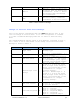
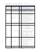
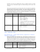
Bit 0: Input 1 change: 0 =
Did not trigger message, 1 =
Triggered message.
Bit 1: Input 1 state: 0 =
Closed, 1 = Open
Bit 2: Input 2 change: 0 =
Did not trigger message, 1 =
Triggered message
Bit 3: Input 2 state: 0 =
Closed, 1 = Open
7
Standard Message
Sub-Type
4
Bits (7:4) Standard message
sub-type code. Value is 3 in
the Input Status Changed
message.
8 RESERVED 3 Bits (2:0) RESERVED in SmartOne
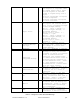
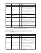
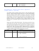
8
Vibration
triggered message
1
Bit (3) – Value 1 = This
message is being sent because
transmit on change of vibration
state is selected and the
vibration just changed state,
or Undesired Vibration state is
selected and the vibration is
in the undesired state. Value
0 = This message is being
transmitted for a reason other
than the above reasons.
8
Vibration bit. 1
Bit (4) – Value 1 = Unit is in
a state of vibration. Value 0
= Unit is not in a state of
vibration.
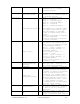
8
2D 1
Bit (5) – Value 1 = GPS data
reported is from a 2D fix.
(Only 3 satellites were used in
the fix.) Value 0 = GPS data
reported is from a 3D fix.
8
Motion 1
Bit (6) – Value 1 = Device was
In-Motion when the message was
transmitted. Value 0 = Device
was At-Rest when the message
was transmitted.
8
Fix Confidence
Bit.
1
Bit (7) 0=High confidence in
GPS fix accuracy, 1=Reduced
confidence in GPS fix accuracy.
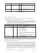
Table 5 – Input Status Changed Message
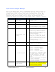
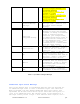
Undesired Input State Message
This is the message that is transmitted when the user has selected for
an undesired input state to cause a different report rate. When this
Mode is enabled, the user defined Undesired Input State report rate
supersedes the At Rest and In Motion report rates when the input(s) is
(are) in an undesired state. The Sub-Type value of this message is 4.
The Input Status portion of byte 7 will indicate which input(s) are in