GLOBTEL GIGARAY 70/80 GHZ USER MANUAL AND TECHNICAL SPECIFICAT IONS
AIR GIGARAY 70 GHz Technical Specification CONTENT 1. 2. FOREWORD ......................................................................................... 3 GLOBTEL GIGARAY SOLUTION ................................................................... 5 2.1. General Description ......................................................................... 5 2.1.1. BASE STATION THROUGHPUT ......................................................... 5 2.1.2. SPECTRUM .................................................
AIR GIGARAY 70 GHz Technical Specification 1. FOREWORD IMPORTANT!!!! Before you is a highly technical transmitting device intended to be used on telecommunication towers. Please be aware of following notices and notes. NOTICE: This device complies with Part 15 of the FCC Rules. Operation is subject to the following two conditions: (1) this device may not cause harmful interference, and (2) this device must accept any interference received, including interference that may cause undesired operation.
AIR GIGARAY 70 GHz Technical Specification AIR GIGARAY 7080G BS FCC ID: 2AWXTAIRGRMP70801 This device complies with Part 15 of the FCC Rules. Operation is subject to the following two conditions: (1) this device may not cause harmful interference, and (2) this device must accept any interference received, including interference that may cause undesired operation.
AIR GIGARAY 70 GHz Technical Specification 2. GLOBTEL GIGARAY SOLUTION 2.1. General Description Globtel GIGARAY system is a unique wireless point to multipoint solution that enables operators to offer their customers full set of triple play services. System is especially suitable for areas with less developed infrastructure as it can be set-up very quickly and can cover wide area at once. It can deliver fiber-like services without the need for construction works, roadblocks and long deployment times.
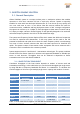
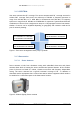
AIR GIGARAY 70 GHz Technical Specification 2.1.2. SPECTRUM One sector antenna has 90° coverage. Four sector antennas with 90° coverage are used to achieve 360° coverage. Each sector can utilize up to 500 MHz of frequency spectrum in range from 69 000 MHz to 71 0000 MHz for downstream and 500 MHz of frequency spectrum in range from 81 000 MHz to 83 0000 MHz for upstream. System allows different combination of sectors from a single sector setup to a fully equipped 4 sector base station.
AIR GIGARAY 70 GHz Technical Specification 2.1.3.2 General technical specification for base station Transmitting section RF output frequency Gain flatness Max throughput (DOCSIS 3.1 ) Max output power Antenna gain 70500-71000 MHz (500MHz band) ±2 dB (-30°C - +70°C) Up to 3,5 Gbps 23 dBm/500MHz 19 dBi (75 degrees) Receiving section RF input frequency Gain flatness Noise figure Max throughput (DOCSIS 3.1 ) Antenna gain 81005 - 80105 MHz (100MHz band) ±2 dB (-30°C - +70°C) 4 dB typ.
AIR GIGARAY 70 GHz Technical Specification DOCSIS 3.
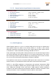
AIR GIGARAY 70 GHz Technical Specification 3. NETWORK SCHEMATICS Range up to 6 Miles (Frequency dependent) DOCSIS 3.1 CMTS Up to 2 Gbps per user Globtel AIR Base Station US: 81 GHz – 83 GHz 40/100G to Core INTERNET BACKBONE Fiber/10G to Tower DS: 69 GHz – 71 GHz EDGE ROUTER IP CORE DOCSIS 3.
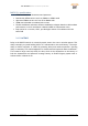
AIR GIGARAY 70 GHz Technical Specification 4. PROTOCOLS AND TECHNOLOGY Globtel AIR Base Station DOCSIS CMTS DOCSIS Remote Phy Ethernet / IP Coax / RF DVBx + DOCSIS Signal Over Globtel Gigaray Globtel AIR Transceiver DOCSIS Cable Modem Ports/connections to peripheral devices: Wifi, Ethernet, PSTN Coax / RF Figure 4: Protocols Globtel AIR fixed wireless system is basically a cable network without cables.
5. BASE STATION INSTALLATION MANUAL AIR GIGARAY 7080G BS FCC ID: 2AWXTAIRGRMP70801 5.
5.1.1. Technical specifications Table 3: Sector antenna specification SPECIFICATION for SECTOR ANTENNA: Parameter Description Receiving Section (upstream) RF Input Frequency IF Output Frequency LO Frequency LO Frequency Stability Gain Gain Flatness Noise Figure Cross talk between output and input 81000-81500 MHz 1000-1500 MHz 80000 MHz ±60Hz (-30;°C~+60°C) 42±5dB typ. 42±6dB (-30°C~+60°C) ±3dB (-30°C~+60°C) 3.8dB typ.
5.1.2. Base station sector assembly The base station sector is assembled from the mounting part and the sector antenna part. Bellow picture showing both components separated.
Before any assembly all nuts and bolts have to be loosen on the mounting par as shown on bellow picture. Nuts and bolts to be loosen Nuts and bolts to be loosen Figure 8: Mounting part in detail We take the nut, washer and bolt from the far end of the eye cable tensioner and from the mounting part. The mounting part is than assembled to the sector antenna part as shown on bellow picture.
Figure 9: Assembly of sector antenna and mounting part When the mounting part is fitted to the sector antenna we insert all the bolts, nuts, washers and begin to tighten them. How the bolts are inserted is shown on bellow picture. The bolt head has to be always on the outside as shown in picture.
Wrench 13 for the screw and the M8 hex nut Bolt M8x25 Washer Sector antenna Mounting part Washer 2x (normal, spring) Nut M8 Figure 10: Bolt assembly The eye cable tensioner is fitted to one of the holes on the sector antenna. The angle between the mounting part and the sector antenna should be app. 95°. Holes on the sector antenna for the tensioner. Angle app. 95° Figure 11: Assembled sector antenna and mounting part Now the sector antenna and mounting part are prepared to be mounted on the mounting pole.
Loosen these bolts. Figure 12: Metal jaws bolts When the bolts are loosen the jaws for the mounting pole can be opened.
5.2 Antenna mounting When the sector antenna is mounted to the desired position on the pole we close the metal jaws and tighten the bolts so much that the antenna stays at the desired height. Now we align the antenna to the desired direction and tighten the bolt with app. 38 Nm strength. Bolts tightened to allow directional positioning of the antenna.
The distance has to be symmetrical mounting pole Figure 15: Distance front and back on jaws Proprietary & Confidential Maribor, 25 June, 2020 Page 19 of 32
5.3 Antenna positioning 5.3.1 Azimuth antenna positioning Step 1: loosen the two M8 bolts with the wrench nu. 13. These bolts join the sector antenna to the mounting part. Bolts connecting the sector antenna and mounting part Figure 16: Positioning guide part 1 Step 2: loosen the nut not the tensioner with wrench nu. 13 Step 3: loosen just a little bit the bolts on both sides of the tensioner with the wrench nu.
Nut on tensioner Bolts on tensioner Tensioner Figure 17: Positioning guide part 2 Step 4: with the tensioner with adjust the antenna to the desired azimuth position Step 5: tighten the nut on the tensioner Step 6: tighten all bolts on the tensioner and the mounting part. 5.3.2 Elevation antenna positioning Step 1: loosen the nuts on the mounting part with wrench nu. 13 marked with B Step 2: loosen the nut on the lever with wrench nu.
Step 3: 2 nuts for pushing or pulling on the lever Step 1: nuts on mounting part Step 2: bolt on the lever with on the mounting part Figure 18: Positioning guide part 3 Step 3: with the help of the 2 nuts on the lever we adjust the tilt to the desired elevation; the default angle is set to 0°.
Scale in degrees of elevation Figure 19: Positioning guide part 4 Step 4: when the tilt is set we tighten both nuts on the lever Step 5: tighten the nut marked with A and then the two nuts marked with B Proprietary & Confidential Maribor, 25 June, 2020 Page 23 of 32
5.4 Connections , Figure 20: AIR Sector antenna 1. 2. 3. 4.
5.4.
5.4.2 Connecting units Cables An indoor unit is connected to an outdoor unit by means of a 2 coaxial cables, one is for downstream and another one for upstream signal, 1 Ethernet cable and 1 power supply cable. Cable length should not exceed 90m.
5.4.3 N-connector installation manual Cut off cable tail right-angled with a small metal saw. The inner conductor has to be kept absolutely round. Move the nut, clamping ring and rubber washer over the cable tail. Hint: With a bit of Vaseline the rubber washer can be move easily over the cable sheath. Remove 7 mm of the outer sheath with a knife. Bend copper braid upwards right-angled. Insert contact sleeve between copper foil and braid until stop. Cut off protruding braid.
5.4.4 M23 Power connector installation manual (outdoor MP side) Push clamp (Pos. 1), reducing sleeve (Pos. 2) with sealing ring (Pos. 3) on the cable. Strip cable outer sheath 40 mm (Pos. 4) Strip the wires (7mm) and crimp on contacts with crimping tool DMC M320 Clip contacts laterally into the contact carrier (Pos. 12). Insert contact support (Pos. 12) in the insert sleeve(Pos. 13). Insert sleeve (Pos. 13) and clamp (Pos. 14) tighten until it stops.
5.4.5 M23 Power connector installation manual (indoor CPS side) Push clamp (Pos. 1), reducing sleeve (Pos. 2) with sealing ring (Pos. 3) on the cable. Strip cable outer sheath 40 mm (Pos. 4) Strip the wires (7mm) and crimp on contacts with crimping tool DMC M320 Clip contacts laterally into the insert sleeve until “click” (Pos. 12). Insert sleeve and clamp (Pos. 14) tighten until it stops.
5.4.
5.4.7 RJ45 connector installation with AMPHENOL RJF 6B Cut cable to required length. Remove the outer jacket (3,8cm) with knife or tool. Assemble Amphenol connector as shown on above schematics. Code A is used. Pull the wire braid back over the outer jacket. Trim off the clear plastic jacket. Untwist and separate all of the conductor pairs. Arrange the conductor in the order shown: 1. White/orange 2. Orange 3. White/green 4. Blue 5. White/blue 6. Green 7. White/brown 8.
5.4.8 Recommended installation steps Below are recommended installation steps. These are suggested steps. In practice the sequence of installation steps can be mixed.