
Owner's manual

12
2000225023C
4 Installation
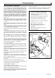
4.7 Positioning the Back Boiler
IMPORTANT. With regards to the Manual Handling Operations,
1992 Regulations, the following lift operation exceeds the
recommended weight for a one man lift.
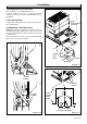
Carefully lift the back boiler by the heat exchanger casting and
place centrally in the builders opening.
The installation centre line is indicated on the base by a notch
on the front of the plate and the fire fixing wall face positioning
line by the front corner edges of the base, see diagram 4.3.
Chatsworth 4 and Dovedale 4 only
The back boiler must be positioned so that a line across the
opening of the wall face coincides with the fire fixing wall face
positioning line, see diagram 4.3.
Please note: This is the only permitted position for the Chatsworth
4 and Dovedale 4.
Use a straight edge across the wall face to make sure that the
back boiler is square to it.
Firelite 4, Contour 4, Miami 4, Heartbeat 4 and
Black Beauty 4 only
The back boiler may be positioned so that a line across the
opening of the wall face coincides with the fire fixing wall face
positioning line. Providing the wall is square the positioning line
can either be set back or set forward up to 10mm from the wall
face, see diagram 4.3.
continued -
Check that the back boiler is level. If packing is required to adjust
the level of the back boiler, use metal shims and pack under the
full width of the base.
Mark through the three fixing holes on the floor protection plate,
see diagram 4.3. Remove the back boiler unit. Drill three holes
using a masonry drill bit to accept appropriate plugs.
4.8 Positioning the Back Boiler - continued
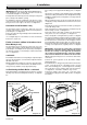
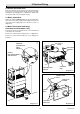
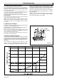
Fit the flueway baffles, from fittings pack, into flueways, ensuring
that they are positioned centrally in the flueways, see diagram
4.5.
Diagram 4.5
9389
BAFFLES (centre in
flueway)
HEAT
EXCHANGER
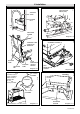
Diagram 4.6
9388
DRAUGHT
DIVERTER
BODY
SECURING SCREWS (2)
Fit the draught diverter body onto the heat exchanger with the
two securing screws supplied in the fittings pack, see diagram
4.6.
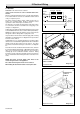
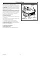
Take the flue sensing tube, packed with the boiler, and fit tubing
nut into brass fitting, located at side of the draught diverter body,
and tighten, making sure the sensing tube is correctly positioned,
see diagram 4.7.
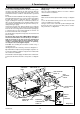
Where a flexible flue liner is being used, fully fit the No.8x
3
/
8
in
self tapping screw provided into the rear of the flue socket as in
diagram 4.8.
Reposition the back boiler unit into the builders opening then
secure with fixing screws.
Refit control/burner assembly leaving the combustion top left
hand securing screw off, see diagram 4.7.
Push fit the silicone tube which is fitted to the flue blockage
safety device, on to the sensing tube, see diagram 4.7.
Fit the sensing tube securing bracket in position, see diagram
4.6, first removing the top left hand combustion chamber screw,
see diagram 4.6. Locate the bottom of the bracket by positioning
the hole in the base of the bracket so that it engages onto the
front left hand nib in the boiler base plate. Secure the top of the
bracket to the combustion chamber with the combustion chamber
securing screw replaced in its original position, see diagram
4.7.
IMPORTANT: Check that the sensing tube is positioned
flat against the combustion chamber side when the sensing
tube bracket securing screw is tightened up and that the
silicone tube is not trapped against the combustion chamber
side. Check also that there are no kinks in the silicone tube.
NOTE: At this point it may be more convenient to fit the water
connections.
Connect the system pipework to the back boiler unit/pre-
plumbed pipework.
If a flexible flue liner is being used, position the liner in to the flue
socket. Using two No.8x
1
/
2
in self tapping screws, coloured
black, from the fittings pack, screw through the two remaining
holes in the flue socket to centralise and secure the flue liner,
see diagram 4.8. Seal with a suitable fire clay cement.
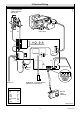
Connect gas supply to gas service cock. Leave gas service
cock and gas fire supply cock in the “OFF” position, see diagram
4.9 and 6.2.