
Owner's manual


25
2000225023C
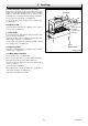
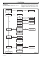
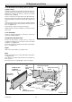
Diagram 8.8
9645
BAFFLES
HEAT
EXCHANGER
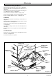
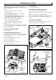
8.8 Flue Blockage Safety Device Assembly
Gain access as relevant part of Section 8.4. Remove any dust
and lint, inspect the pilot for damage. Remove the sensing tube
adapter, to clean, blow through, do not use a wire or sharp
instrument. If necessary replace the flue blockage safety device.
Check for the correct spark gap, see diagram 8.6.
To remove the safety device, remove the two securing screws,
see diagram 8.7.
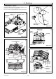
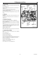
8.9 Ignition Lead
Inspect the ignition lead for wear or damage, clean or replace
as necessary, see diagram 8.7.
8.10 Electrode
Ensure the electrode is in line with the earth post and the spark
gap is as shown in diagram 8.6.
Inspect the electrode for wear or damage, clean, or replace the
flue blockage safety device, see diagram 8.7.
To remove the safety device, disconnect the pilot tube nut and
two securing screws, see diagram 8.7.
8.11 Sensing Lead
Inspect the sensing lead for wear or damage, clean, or replace
as necessary, see diagram 8.7.
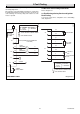
8.12 Back Boiler Flueways
Lift out the flue baffles, see diagram 8.8.
Place a sheet of paper in the base of the combustion chamber.
Clean the boiler flueways with a suitable stiff brush.
To make sure that the flueways are clean, view with the aid of
a mirror or reflector.
Remove the paper and debris.
When refitting make sure that the baffles are seated and are
centred in the flueways see diagram 8.8.
Now refit the control/burner assembly.
8 Servicing
(Baffles must be
positioned
centrally in the
flueways)