Betacom Installation and Servicing 24c G.C. No. 47-019-08 30c G.C. No. 47-019-09 High Efficiency Condensing Combination Boilers 23 22 21 24 20 1 19 60 70 80 90 2 50 3 40 17 30 18 ON bar 4 5 0 6 7 11 10 9 8 www.glow-worm.co.
Guarantee Registration Thank you for installing a new Glow-worm appliance in your home. Glow-worm appliances are manufactured to the very highest standard so we are pleased to offer our customers a Comprehensive First Year Guarantee. We recommend you complete and return as soon as possible your guarantee registration card. If your guarantee registration card is missing you can obtain a copy or record your registration by telephoning the Glow-worm Customer Service number 01773 828100.
These instructions consist of, Installation, Servicing, Fault Finding, Replacement of Parts and Spares. The instructions are an integral part of the appliance and must, to comply with the current issue of the Gas Safety (Installation and Use) Regulations, be handed to the user on completion of the installation.
WARNINGS Gas Leak or Fault Turn off the gas emergency control valve immediately. Eliminate all sources of ignition, i.e.smoking, blowlamps, hot air guns etc. Do not operate electrical lights or switches either on or off. Open all doors and windows, ventilate the area. Metal Parts This boiler contains metal parts (components) and care should be taken when handling and cleaning, with particular regard to edges. Sealed Components Under no circumstances must the user interfere with or adjust sealed parts.
Statutory Requirements CE Mark This boiler meets the requirements of Statutory Instrument, No. 3083 The Boiler (Efficiency) Regulations, and therefore is deemed to meet the requirements of Directive 92/42/EEC on the efficiency requirements for new hot water boilers fired with liquid or gaseous fuels. Type test for purposes of Regulation 5 certified by: Notified body IMQ 51BP2727 CE Directives 90/396/EEC. 51BP2728DR CE Directives 92/42/EEC.
Boiler Design Boiler Design Condensate Drain These boilers are designed for use as part of a sealed water central heating system with fully pumped circulation. The pump, expansion vessel and associated safety devices are all fitted within the boiler. The appliance has a built in frost protection device that protects the boiler from freezing. Once the controls are set the boiler operates automatically. A plastic drain pipe must be fitted to allow discharge of condensate to a drain.
Servicing, Maintenance and Spare Parts Servicing and Maintenance To ensure the continued efficient and safe operation of the boiler it is recommended that it is checked and serviced as necessary at regular intervals. The frequency of servicing will depend upon the particular installation conditions and usage, but in all cases the boiler must be serviced at least once a year.
Boiler Specification Boiler Design The appliance has a built in frost protection device that protects the boiler from freezing. Once the controls are set the boiler operates automatically. These boilers are designed for use as part of a sealed water central heating system with fully pumped circulation. The pump, expansion vessel and associated safety devices are all fitted within the boiler.
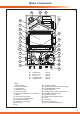
14532 14 15 12 t the rea 16 r A 13 t the rea r A Boiler Components 11 10 9 17 8 18 7 6 19 5 20 4 21 3 22 e t th rea r 23 A 2 24 1 A B C D E A - Heating Flow B - D.H.W. Outlet C - Gas Inlet D - Cold Water Inlet E - Heating Return Key 1 - D.H.W. Sensor 2 - Diverter Valve Motor 3 - Diverter Valve 4 - Condensate Trap 5 - Limit Thermostat 6 - Expansion Vessel (At rear of the boiler) 7 - Burner 8 - Flame Sensor Electrode 9 - C.H.
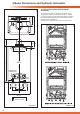
2 Boiler Dimensions and Hydraulic Schematic 14334 150 330 170 All dimensions are given in millimetres (except as noted). The general arrangement of the boiler is shown in diagram 2.1 and the hydraulic and gas schematics diagrams, showing the central heating hydraulic circuit and domestic hot water hydraulic circuit in diagram 2.2. The data label is positioned on the control box back cover. 130 14335 105 2.
3 Boiler Location, Clearances and Ventilation 3.1 Location This boiler is not suitable for outdoor installation. This boiler may be installed in any room, although particular attention is drawn to the installation of a boiler in a room containing a bath or shower where reference must be made to the relevant requirements. This boiler is suitable for installation in bathroom zones 2 and 3. In GB this is the current I.E.E. WIRING REGULATIONS and BUILDING REGULATIONS.
4 Flue Options and Terminal Clearances Top horizontal telescopic flue (Ø60/100) Part No. A2043600 - Section 9, page 21 Top horizontal standard flue (Ø60/100) Part No. A2043400 - Section 9, page 25 Plume Management Kit basic set, white, concentric flue (Ø60/100) - Part No. A2044100 for use with Part No. A2043400 and Part No. A2043600 - Section 9, page 35 Vertical Flue Vertical Flue Adapter, concentric flue (Ø60/100) Part. No.
4 Flue Options and Terminal Clearances 4.1 Flue Options There are various flue options to choose from as illustrated in diagram 4.1. The flue lengths and installation are described in section 9. 4.
5 Water System - Heating 14561 5.1 General The boiler is designed to operate on fully pumped, pressurised sealed systems operating at a maximum of 3bar pressure and maximum design flow temperature of 85°C. 5.2 Safety Valve The safety valve is an integral part of the boiler and it cannot be adjusted.The pipe from the safety discharge valve must not discharge above an entrance, window or any type of public access area. 5.
5 Water System - Domestic Hot Water 5.10 Water Pressure To obtain the best hot water performance from your boiler it is suggested that the cold water supply to the boiler is the first draw off from the incoming mains supply. NOTE: The boiler will not operate unless there is a minimum pressure of 0.25 bar (3.6 Ibf/in2) with a flow rate of 2.5 l/min. The minimum working pressure to obtain the maximum domestic flow is:24c 0.7 bar (10.15 Ibf/in2) 30c 0.7 bar (10.
6 Installation Preparation 14339 CHECK IF 230V thermostat plug is required to fit to PCB board. COLD WATER FILTER WALL HANGING BRACKET D.H.W OUTLET C.H. ISOLATION VALVE RETURN COLD WATER ISOLATION VALVE INLET GAS ISOLATION VALVE SEALING WASHERS (5 OFF) CONDENSATE OUTLET PIPE WALL TEMPLATE SAFETY DISCHARGE PIPE C.H. ISOLATION VALVE FLOW Diagram 6.1 6.
6 Installation Preparation Take the wall template from the document pack and place in the desired position on the wall, giving due consideration to the required boiler clearances, see section 3, and the flue you are fitting. Mark the position of the flue centre, if fitting a side flue, extend the flue centre line into the corner then 170mm along the adjacent wall, see diagram 6.3.
7 Boiler fixing, Gas / Water / Safety Discharge Connections 14347 ISOLATION VALVES SHOWN CLOSED Diagram 7.1 14348 7.1 System connection Connect the isolation valves including sealing washers and cold water inlet filter to the boiler ensuring the washers are fitted correctly, see diagram 7.1. Make sure the isolation valves are closed. 7.2 Safety Discharge Pipe Connect the safety discharge pipe, see diagram 7.2. This must be extended, using not less than 15mm o.d.
8 System Pipes and Condensate Connections 8.1 Condensate Trap Connection 14527 A flexible condensate outlet pipe is supplied and should be used to couple the condensate trap to a 22mm to 25mm O.D. non corrosive plastic pipe (overflow pipe), see diagram 8.1. NOTE: the pipe should have a fall of a least 2.5o 44mm/metre away from the boiler. Condensate should, if possible be discharged into the household internal drainage system.
13000 8 Condensate Connections Diagram 8.
9 Telescopic Flue - Length, Preparation and Installation 9.1 Flue Length and Restrictors Horizontal Telescopic Flue 14350 The maximum permissable horizontal flue length is 2.5 metres plus the flue terminal assembly, this can be achieved by use of the accessories, see diagram 9.3. However should an additional 90º or 2 x 45º elbows be used then the length MUST be reduced by 1 metre. The diagram 9.1 shows the length achievable by using the kit A2043600.
9 Telescopic Flue - Length, Preparation and Installation 14005 Diagram 9.2 15532 Diagram 9.
9 Telescopic Flue - Length, Preparation and Installation 14471 9.2 Horizontal Telescopic Flue - A2043600 Refer to diagram 9.2 for kit contents. 9.3 REAR Flue If a wall thickness is between 210mm min. to 420mm max. then the flue can be used without extensions. Temporarily secure the flue elbow, measure the distance from the outside wall to the butt joint, see diagram 9.4. If the measurement ‘Y’ exceeds 525mm, then the appropriate length of extension pipe is required.
9 Telescopic Flue - Length, Preparation and Installation 12929 Diagram 9.7 12977 Diagram 9.8 14474 Diagram 9.9 24 9.5 Flue Fitting With the air duct seams aligned and the flue set to the required length ‘Y’, mark the securing hole position in the air duct. Drill a 3mm diameter hole at this position, take care not to pierce the inner flue duct. Secure with screw provided and tape the joint, see diagram 9.7. Fit the sealing collar onto the locating ring on the flue terminal, see diagram 9.8.
9 Standard Flue - Length, Preparation and Installation 9.6 Flue Length The maximum permissable horizontal flue length is 5.6 metres for Betacom 24c and 4.6 metres for Betacom 30c, this can be achieved by use of the accessories, see diagram 9.12. However should additional 90º or 2 x 45º elbows be used then the length MUST be reduced by 1 metre. The diagram 9.10 shows the length achievable by using the kit A2043400.
9 Standard Flue - Length, Preparation and Installation 13222 Diagram 9.11 15532 Diagram 9.
9 Standard Flue - Length, Preparation and Installation 14471 9.7 Standard Horizontal Flue - A2043400 Refer to diagram 9.11 for kit contents. 9.8 REAR Flue Temporarily secure the flue elbow, measure the distance from the outside wall to the butt joint, see diagram 9.13. If the measurement ‘Y’ exceeds 665mm, then the appropriate length of extension pipe is required. The minimum dimension is 180mm to suit a 75mm min wall thickness. The flue can project to a maximum of 600mm, refer to diagram 9.14. 9.
9 Standard Flue - Length, Preparation and Installation 12847 Diagram 9.16 14472 Diagram 9.17 28 9.10 Flue Fitting Remove the flue elbow. Separate the flue duct from the terminal by twisting to release the terminal catch, then pull out of the retaining seal, refer to diagram 9.16. The flue duct cutting length (L + 11mm.) is shown in diagram 9.16. The air duct should be cut at the opposite end to the terminal The plastic flue duct MUST be cut at the opposite end to the terminal catch.
9 Vertical Flue - Length, Preparation and Installation 9.11 Vertical flue 15534 The vertical flue system is available as an option where the boiler position does not permit the use of the top horizontal flue system. The system is made up from accessories. The accessories include terminal assembly, bends 45º and 90º, flue extensions, fixing bracket and appropriate weather collar,see diagram 9.19. The maximum permitted straight flue length is 6,8 metres for Betacom 24C, 5,8 metres for Betacom 30C.
9 Vertical - Flue Length, Preparation and Installation 12969 9.12 Flue Installation Refer to diagram 9.20 and secure the flue adapter in position on top of the boiler with four screws supplied, NOTE: The rubber ‘O’ rings of each section should be lubricated prior to assembly. Do not use mineral oils or grease, silicon grease or water is recommended.
9.15 Completion of Installation With the flue terminal positioned in the roof the length of the final pipe can be determined. If a telescopic length cannot be used, then a standard flue length can be cut to make the correct length. Cut the flue to the desired length measuring from the ‘O’ ring end and discard the plain end of the tube. The cuts must be square and made free of burrs to allow correct assembly. NOTE: The flue pipe is 10mm longer than the air pipe, see diagram 9.23.
14530 9 Twin Flue - Length, Preparation and Installation Secure long flue lengths (horizontal & vertical) to walls or ceiling at every joint or on straight flue runs at every joint and every metre flue run. Diagram 9.
9 Twin Flue - Length, Preparation and Installation 12970 9.16 Twin flue The twin flue system is available as an option when the top horizontal or vertical flue system is not appropriate. The system can provide an independent horizontal air inlet and flue outlet, horizontal air inlet and vertical flue outlet or vertical air inlet and flue outlet via a concentric terminal. The system is made up from accessories, see diagram 9.25. NOTE: The air and flue outlets do not have to be equal lengths.
9 Twin Flue - Length, Preparation and Installation 14531 9.19 Boiler Connection Place the twin flue adaptor onto the outlet of the boiler with the air inlet to the left hand side, see diagram 9.26. Secure the adaptor to the top panel with the screws provided. Care should be taken when inserting the screw through the hole in adaptor top. To facilitate engagement, it is recommended that the rubber ‘O’ rings are lubricated with silicone grease or water prior to assembly. 9.
12997 9 Plume Management Kit 9.25 Plume Management Kit The Plume Management Kit: Part No. A2044100 (white) or A2044000 (black) can be used to overcome many site issues. The Plume Management Kit will fit to the Top Horizontal Telescopic, Rear Horizontal Telescopic and Standard Horizontal Flue. This enables the flue products to exhaust further away from the boiler, thereby reducing the impact of pluming.
10 Electrical Connection WARNING: UNDER NO CIRCUMSTANCES MUST ANY MAINS VOLTAGE BE APPLIED TO ANY OF THE TERMINALS ON THE 24V CONNECTION. The 24V low voltage room thermostat terminal block is located on the left side of the rear cover of the controls box. To access the 24V low voltage room thermostat terminal block remove the front panel secured with two screws, lift off the two retaining lugs, see diagram 10.1. Carefully pull forward and down the controls fascia, see diagram 10.2.
If a mains voltage thermostat is to be used. Unclip the two front retaining clips on the controls fascia, see diagram 10.3. Unclip and carefully pull down the control circuit board cover, see diagram 10.4. to access the mains voltage connection located on the printed circuit board, see diagram 10.5. On connection of a mains voltage room thermostat to the boiler, the bridge wire on factory fitted plug must be cut to fit a connector block.
14571 11 Commissioning PUMP VENT PLUG ISOLATION VALVES SHOWN OPEN IMPORTANT: At the time of commissioning, complete all relevant sections of the Benchmark Checklist located in the centre pages of this document. Diagram 11.1 IMPORTANT NOTE: In order to maintain the appliances warranty; after initial filling the heating system must be thoroughly flushed using a propriety cleanser to remove foreign material and contaminants. Do Not operate the boiler without water.
STANDBY INDICATOR PRESSURE GAUGE TIMER DISPLAY 24 40 60 70 80 21 90 bar 3 3 17 4 1 14 6 5 0 15 bar 4 16 0 20 1 18 2 1 50 22 2 30 23 19 ON 14333 11 Commissioning 7 13 11 10 9 8 FUNCTION SWITCH 12 DOMESTIC HOT WATER TEMPERATURE CONTROL CENTRAL HEATING TEMPERATURE CONTROL Diagram 11.4 11.3 Control Panel Functions, diagram 11.4. 11.
11.5 Setting Operational Pressure Minimum setting Remove the sensing tube from the gas valve. Remove one lead from the modulating gas valve coil, see diagram 11.6. Refer to diagram 11.7. Connect a suitable pressure gauge the pressure outlet of the gas valve. Turn the boiler’s function switch to the ‘Winter’ position. (Heating and Hot Water), see diagram 11.4 Turn the central heating temperature control to maximum setting. Remove the protective cover from the gas valve adjuster.
15525 11 Commissioning Diagram 11.7 14586 SECURING SCREWS GAS ISOLATION VALVE SUPPLY PIPE CONNECTION Diagram 11.8 11.6 Checking the gas rate The boiler is fitted with a fully modulating automatic gas valve. With all other gas appliances turned off measure the gas rate at the gas meter.
11 Commissioning 14553 DIP ON 1 2 3 4 5 6 7 8 P7 8 DIP SWITCHES IN THE OFF POSITION P5 Diagram 11.10 P2 14565 P4DIP SWITCH ON DIP ON POSITION 1 2 3 4 5 6 7 ON 8 DIP DIP SWITCH OFF POSITION 1 2 3 4 5 6 7 8 Diagram 11.11 ON DIP 14554 The boiler incorporates 4 potentiometers and a bank of dip switches to allow adjustment to its pre-set parameters. These are situated on the rear of the control panel.
11 Commissioning 11.8 Completion GB: It is a requirement that the “Benchmark” Installation, Commissioning and Service Record is completed and left with the user. IE: it is necessary to complete a “Declaration of Conformity” to indicate compliance to I.S.813. An example of this is given in the current edition of I.S.813. 11.9 Instruct the User ● Demonstrate, then instruct the User about the lighting procedure and heating system controls operation.
11 Commissioning - Nat. Gas (G20) to LPG (G31) Conversion 14555 11.10 LPG CONVERSION - all models IMPORTANT: Gas conversion must be carried out by a competent person approved at the time by the Health and Safety Executive. Isolate the boiler from both the Gas and Electricity supplies. The burner must be removed from the boiler by removing, the front panel, hermetic chamber cover and combustion chamber cover. Remove the two securing screws, one on each side of the burner, see diagram 11.13.
11 Commissioning - Nat. Gas (G20) to LPG (G31) Conversion Factory settings for DIP switches DS1 DS2 DS3 DS4 DS5 DS6 DS7 DS8 Betacom 24c NG OFF OFF OFF OFF OFF OFF OFF OFF Betacom 24c LPG OFF OFF OFF OFF OFF OFF ON OFF Betacom 30c NG OFF OFF OFF OFF OFF OFF OFF ON Betacom 30c LPG OFF OFF OFF OFF OFF OFF ON ON To set the Maximum Setting: Connect a suitable pressure gauge to the burner pressure test point on the gas valve.
12 Servicing IMPORTANT NOTES: 1. To ensure the continued efficient and safe operation of the boiler it is recommended that it is checked and serviced at regular intervals. The frequency of servicing will depend upon the particular installation and usage, but in all cases the boiler must be serviced at least once a year. 2. It is the Law that any servicing is carried out by a competent person approved at the time by the Health and Safety Executive. 3.
12 Servicing COMBUSTION CHECK AND SETTING GAS VALVE ● Remove the front casing panel, see diagram 10.1 and hinge down the control box. Taking care not to touch any internal components, proceed as follows: ● Connect the CO2 combustion analyser to the relevant test point.
14540 RETAINING LUGS 14495 12 Servicing SECURING SCREWS (6 OFF) INNER CASING PANEL VIEWING WINDOW 23 22 21 20 24 19 1 18 60 70 80 90 3 50 1 14 0 5 bar 15 4 40 16 30 6 9 8 3 7 4 10 bar 11 0 12 1 13 2 SECURING SCREWS 14573 Diagram 12.2 COMBUSTION CHAMBER COVER ELECTRICAL CONNECTIONS VIEWING WINDOW Diagram 12.
12 Servicing Disconnect the electrical connections and air pressure switch connection tubes from the fan, remove the fan securing screw and withdraw fan from fan hood with its 56º bend, see diagram 12.5. SPARK GAP 4mm 14566 12.2 Fan removal 12.3 Burner removal BURNER Remove the burner assembly from the combustion chamber as follows: Pull off the ignition and flame electrode leads from mains circuit board and remove the wires with grommet from the combustion chamber base, see diagrams 12.6 and 12.7.
HALL EFFECT SENSOR r r AIR PRESSURE SWITCH GAS CONTROL VALVE FAN 14593 13 Fault finding r r PUMP g g g/y r LIMIT THERMOSTAT WATER PRESSURE SWITCH r DOMESTIC HOT WATER SENSOR r w w w g w IGNITION ELECTRODES FLAME (IONISATION) ELECTRODE w THREE WAY VALVE CENTRAL HEATING NTC SENSOR r r WATER FLOW SENSOR 230V ROOM THERMOSTAT CONNECTION (high voltage) r OVERHEAT SAFETY THERMOST AT w g/y w FUSES (2A) br r w g br r w r bk r PRINTED CIRCUIT BOARD 24V ROOM THERMOSTAT CONNECTION (l
13 Fault finding The following checks should be performed before proceeding onto specific diagnostics: Check the external electrical supply to the boiler is on and a supply of 230V is present at the ‘L’ and ‘N’ terminals. Check the electrical installation and boiler, carry out tests for earth continuity, polarity, short circuit and resistance to earth, using a suitable multimeter. An aid to test Remove the front casing panel, see diagram 10.1 and hinge down the control box.
13 Fault finding Check electrical supply central heating sensor and frost protection. 14496 13.2 Fault finding chart 1. 6 Diagram 13.
13 Fault finding Check domestic hot water operation. 14497 13.2 Fault finding chart 2. 4 Diagram 13.5 Check central heating operation. 14498 13.3 Fault finding chart 3.
13 Fault finding Check domestic hot water operation. 14499 13.4 Fault finding chart 4. 6 Diagram 13.7 Check domestic hot water and central heating modulation 14500 13.5 Fault finding chart 5. Diagram 13.
13 Fault finding Check ignition system. 15558 13.6 Fault finding chart 6. Diagram 13.
14 Replacement of parts 14.1 Draining of Boiler To prevent the need to drain the entire heating system when replacing the boiler’s integral pump, expansion vessel, safety relief valve and pressure sensor, the boiler’s hydraulic circuit may be isolated from the central heating circuit by closing the boilers isolation valves. Opening the discharge safety valve will then drain the boiler’s hydraulic circuit. NOTE: clean the valve seat to ensure it seals before re-filling the boiler.
14 Replacement of parts For access, refer to section 14.1. The air pressure switch is located above the expansion vessel, see diagram 14.3. Remove the sensing tubes and electrical connections from the air pressure switch, noting which tube is connected to which port. Remove the air pressure switch by unclipping it from the bracket. Fit the replacement air pressure switch in reverse order of removal. For access, refer to section 14.1. Turn off and isolate the electrical supply.
14.10 Pump body UNION NUT SECURING SCREWS SECURING SCREW AUTOMATIC AIR VENT CLIP 14583 Diagram 14.9 14562 For access, refer to section 14.1. Remove the motor as described in section 14.9. Remove the low water pressure sensor refer to section 14.11. Remove the secondary heat exchanger as described in section 14.12. Refer to diagram 14.7. Remove the expansion vessel pipe by removing the clip on the pump body. (clip at the rear, see diagram 14.8.
14 Replacement of parts For access, refer to section 14.1. Drain the boiler circuit, refer to section 14.2. Locate the low water pressure sensor at the front right hand side of the boiler and remove the electrical sensors connections, see diagram 14.11. Remove the low water pressure sensor by turning it in an anticlockwise direction. Fit the replacement sensor in reverse order of removal ensuring all washers are fitted. Replace damaged washers as necessary.
14.14 Gas valve Minimum setting Remove the sensing tube from the gas valve. Remove one lead from the modulating gas valve coil, see diagram 14.15. Refer to diagram 14.16. Connect a suitable pressure gauge to the pressure outlet of the gas valve. Turn the boiler’s function switch to the ‘Winter’ position. (Heating and Hot Water), see diagram 11.4 Turn the central heating temperature control to maximum setting. Remove the protective cover from the gas valve adjuster.
15525 14 Replacement of parts GAS ISOLATION VALVE SECURING SCREWS 14586 Diagram 14.16 SUPPLY PIPE CONNECTION Diagram 14.17 Checking the gas rate The boiler is fitted with a fully modulating automatic gas valve. With all other gas appliances turned off measure the gas rate at the gas meter.
14.15 Expansion vessel SECURING NUT OVER HEAT SAFETY THERMOSTAT ELECTRICAL CONNECTIONS Diagram 14.17 14.17 Pressure safety relief valve For access, refer to section 14.1. Drain the boiler circuit, refer to section 14.2. Refer to diagram 14.18. Disconnect the discharge pipe on the outlet of the safety relief valve. Unscrew to remove the safety relief valve from the R.H. hydroblock and retain the o-ring for use on reassembly, replace as necessary.
14 Replacement of parts 14.21 Three way valve motor For access, refer to section 14.1. Drain the boiler circuit, refer to section 14.2. Refer to diagram 14.12. Remove the secondary heat exchanger, see section 14.12. Remove the pump assembly, see section 14.9. and 14.10. Remove the section of the hydroblock from the pump by releasing the clip. Release the heat exchanger outlet pipe nut and rotate the pipe for easy removal of the left section of the hydroblock.
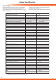
15 Spare parts 15.1 Spare Parts When ordering spare parts, contact Glow-worm’s own service organisation using the telephone number on the inside front cover of this booklet. Please quote the name of the appliance and serial number, to be found on the data label. If ordering from British Gas also quote the G.C. number of the part. No. 1 64 Description Model Fan Part No. No.
1 14595 15 Spare parts 2, 3 4 10 6 7 9 12 11 5 13 8 14 17 15,16 28, 29 18, 19 22 20, 21 23 27 24 26 25 Diagram 15.
16 Manual Handling IMPORTANT. With regards to the Manual Handling Operations, 1992 Regulations, the following lift operation exceeds the recommended weight for a one man lift. General recommendations when handling Clear the route before attempting the lift. Ensure safe lifting techniques are used – keep back straight – bend using legs. Keep load as close to body as possible. Do not twist – reposition feet instead. If 2 persons performing lift, ensure co-ordinated movements during lift.
17 Declaration of conformity 67
-03 07.09 Because of our constant endeavour for improvement, details may vary slightly from those shown in these instructions. Glow-worm, Nottingham Road, Belper, Derbyshire. DE56 1JT www.high-efficiency.