
User guide


17
6 Installation Preparation
Diagram 6.3
14549
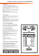
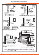
6.3 Wall Template
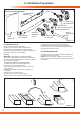
Take the wall template from the document pack and place in
the desired position on the wall, giving due consideration to
the required boiler clearances, see section 3, and the ue you
are tting.
Mark the position of the ue centre, if tting a side ue, extend
the ue centre line into the corner then 170mm along the
adjacent wall, see diagram 6.3.
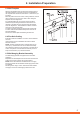
For extended side ues, the ue hole centre should be
determined by extending the dashed inclined line on the
template to the side wall, then 149mm along the adjacent
wall, see diagram 6.2. This dashed line is drawn at 44mm/
metre (2.5°) rise from the boiler.
To allow for the ue passing through the wall at this angle
a 125mm hole should be drilled irrespective of internal or
external installation.
Remove the wall template whilst drilling the ue hole.
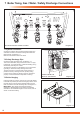
6.4 Flue Hole Cutting
External access ue installation can use a 105mm diameter
core drill.
Internal access only ue installation will need a 125mm
diameter core drill.
NOTE: The ue is designed with an internal fall of 44mm/
metre (2.5°), therefore the hole can be drilled horizontally.
If ue extension pipes are to be used then a core drill size of
125mm is required. This will allow the extension pieces to
slope at 44mm/metre (2.5°) towards the boiler.
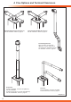
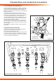
6.5 Wall Hanging Bracket Assembly
The Wall Hanging Bracket is supplied in the main boiler
packaging.
Reposition the wall template over the ue hole and mark the
position of the xing holes for the hanging bracket.
NOTE: Due to the varied site conditions we do not supply
xings and advise that the installer should supply those which
are suitable.
Drill xing holes using a 8.5mm. drill bit and insert suitable
wall plugs. Secure the wall hanging bracket to the wall.