
User guide


29
Diagram 9.18
15534
9 Vertical Flue - Length, Preparation and Installation
9.11 Vertical ue
The vertical ue system is available as an option where the
boiler position does not permit the use of the top horizontal
ue system.
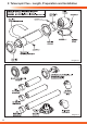
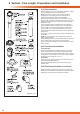
The system is made up from accessories. The accessories
include terminal assembly, bends 45º and 90º, ue
extensions, xing bracket and appropriate weather collar,see
diagram 9.19.
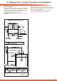
The maximum permitted straight ue length is 6,8 metres for
Betacom 24C, 5,8 metres for Betacom 30C.
for each 90º or 2x45º bends tted, the maximum length
must be reduced by 1 metre, see diagram 9.18.
NOTE: 2x45º bends can replace 1x90º bend if necessary.
When using 90º bends any horizontal extension pipe should
be inclined by a minimum of 44mm/metre (2.5º) towards the
boiler to facilitate condense removal, see (a) in diagram 9.18.
Alternatively use 45º bends to avoid horizontal runs, see (b)
in diagram 9.18.
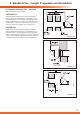
The terminal siting should be as shown in diagram 4.2.
Measure the distance of ue length required for the
installation.
The ue must be designed with a continuous fall towards the
boiler.
The maximum permitted straight flue length
is 6,8 metres for Betacom 24C, 5,8 metres
for Betacom 30C, for each
90°or 45°x2
bends fitted, the maximum
length must be
reduced by 1 metre.
w
w
E
1
E
1
E
2
E
2
Maximum flue (calculated equivalent) length
w, x, y, z, E
1
and E
2
should be less than 6.8 m for
Betacom 24c, 5.8 m for Betacom 30c