
User guide


37
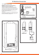
230V ROOM
THERMOSTAT
CONNECTION
ON PRINTED
CIRCUIT BOARD
230V ROOM
THERMOSTAT
49 50
X20
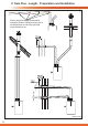
10 Electrical Connection
ON 30 40 50 60 70 80 90
bar
14539
1453814479
14637
Diagram 10.3
Diagram 10.4
Diagram 10.5
Diagram 10.6
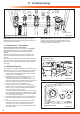
10.3 System Controls 230V
If a mains voltage thermostat is to be used.
Unclip the two front retaining clips on the controls fascia, see
diagram 10.3.
Unclip and carefully pull down the control circuit board cover,
see diagram 10.4. to access the mains voltage connection
located on the printed circuit board, see diagram 10.5.
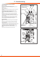
On connection of a mains voltage room thermostat to the
boiler, the bridge wire on factory tted plug must be cut to t a
connector block.
NOTE: Mains powered thermostats must be connected
directly to the mains circuit board as indicated in diagram
10.6.
NOTE: Ensure that the polarity of the mains connection is
correct as reversed polarity may cause the appliance to
malfunction.
NOTE: While the boiler’s main pcb, pump, three-way valve
and gas valve are supplied at 230V AC., all other components
and associated circuits are supplied at low voltage.
NOTE: When re-assembling, take care NOT TO TRAP the
cables and wires.
NOTE: Connection to the mains electrical supply must be
maintained at all times in order to provide domestic hot water,
frost protection and pump over-run facility.
Ensure that the boilers electrical supply is not interrupted by
any external controls.
10.4 Electrical Connections - Testing
Carry out preliminary electrical system checks prior to making
the nal connection as below:
1. Test insulation resistance to earth of mains cables.
2. Test the earth continuity and short circuit of cables.
3. Test the polarity of the mains.
RETAINING CLIPS
BRIDGE PLUG
RETAINING CLIPS
CONTROLS FASCIA
CONTROLS CIRCUIT
BOARD COVER
PRINTED CIRCUIT
BOARD