
Manual

0020145065_01 - 09/12 - Glow-worm
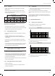
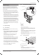
14.2 Fault memory
• This menu allows you to display the 10 most recent failure
codes registered by the appliance.
• In order to display the fault code memory, simultaneously
press the buttons
and for more than 7 seconds.
• The screen will display the rst fault "1." (record) and after
"XX" (fault code).
• To display the other faults registered by the appliance, press
the button
or .
• Press button
for more than 3 seconds to exit this menu.
• To erase the fault memory registered by the appliance, consult
the “Installation adjustments” chapter and use code “d.94”.
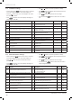
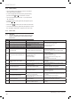
14.3 Fault codes
i
IMPORTANT:
The faults described in this chapter should be carried
out by a qualied engineer and if needed by the After
Sales Service.
Fault
codes
Description Cause Solution
F00 Flow heating temperature sensor fault Sensor open circuit
• Check the sensor’s connections.
• Check the wiring harness.
• Check the sensor.
F01 Return heating temperature sensor fault
Return heating temperature sensor
disconnected
F10 Flow heating temperature sensor fault Sensor short-circuit
F11 Return heating temperature sensor fault Return heating temperature sensor shorted.
F20 Overheating fault Overheating safety device activated (97°C)
• Check the operation of the pump.
• Check the wiring harness.
• Check that the ow and return heating isolation
valves are open.
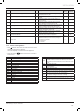
F22
Water pressure of the installation (<0.3
bar)
Return water valve closed
Pump disconnected
Leak in the installation
• Fill the installation.
• Purge the installation.
• Check the pump connections.
• Check the ow and return heating sensor
connections.
• Check that there are no leaks.
F23
Maximum temperature dierence
reached between return and ow
heating
Water circulation fault
• Check the ow and return heating sensor
connection.
• Check the pump speed.
F24 Water circulation fault
Malfunction of the pump (excessively rapid
temperature increase)
• Check that the ow and return heating isolation
valves are open.
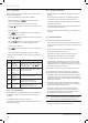
F26 Fault in gas valve motor. Disconnected or defective cables
• Check the gas valve connections.
• Check the operation of the gas valve.
• Check the operation of the condensate pump (option).
F27 Flame detection fault. Abnormal ame detection
• Check the ame detection electrode.
• Check the main board.
• Check the igniter unit.
F28 Ignition fault
No return gas / Insucient gas ow
Gas valve incorrectly adjusted
Defective ring electrode and ame control /
Defective igniter unit
• Check the return gas circuit (gas valve open).
• Check the observe the ame picture and check the
CO
2
setting.
• Check the igniter unit connections.
• Check the state of the electrode (corrosion).
F29 Loss of ame during operation
F32 Incorrect air pressure Incorrect fan speed.
• Check the entire ue system.
• Check the fan’s electrical connections.
F49 EBUS voltage fault
Fault in EBUS line
Short circuit in EBUS connector
• Check that the eBus controls are tted and wired
correctly.
MAINTENANCE
- 28 -