Glow•worm Clearly Heat Recovery Atmosorb Installation and Servicing Instructions HRD 275 Part. No. 0010008891 HRD 350 Part. No. 0010008892 Mechanical Ventilation system with heat recovery www.glow-worm.co.
Guarantee Glow-Worm guarantees that the high-quality product that you have purchased is free from any manufacturing defects. This guarantee is in addition to and does not replace nor limit your statutory rights. Your local Trading Standards office may advise you.
These instructions consist of, Installation, Servicing, Fault Finding. The instructions are an integral part of the unit and must, to comply with the current Regulations, be handed to the user on completion of the installation.
Statutory Requirements IMPORTANT Where no British Standards exists, materials and equipment should be fit for their purpose and of suitable quality and workmanship.The installation of this unit must be carried out by a competent person approved at the time by the Health and Safety Executive and in accordance with the rules in force in the countries of destination. Manufacturer’s instructions must not be taken as overriding statutory requirements.
Important Information Notes on the documentation The following notes serve as a guide for the entire documentation. Further documents apply in combination with this installation instructions. We accept no liability for any damage caused by non-observance of these instructions. Documentation Storage Give this installation manual and all accompanying documents to the operator who will store them so that they are available when required.
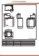
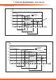
A 14882 1 Technical Specification 18 2 200 D 645 709 9 86 41 ØC (4 x) 3 15 53 441 B Y-Y 14 2 400 4 50 403 F E 115 680 A B C D A F 6 Atmosorb HRD 275 77 471 ø 150/ø 160/ø 178 ø 150/ø 160/ø 178/ø 198 102 210 Overall Dimensions Atmosorb HRD 350 127 521 ø 180/ø 198 ø 150/ø 160/ø 178/ø 198 122 240 Remarks Pipe diameter to be selected for all 4 air connections Pipe diameter to be selected for the bypass connection
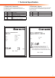
1 Technical Specification 1.1 Data Label - Atmosorb 1.2 Data Label - Bypass Units Units The identification plate is positioned below the unit. The indications given on the identification plate have the following meaning: Value Description You can find the identification plate on the top of the device.
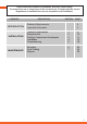
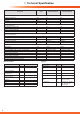
1 Technical Specification Description Units Atmosorb HRD 275 Atmosorb HRD 350 Air specifications Maximum air volume flow Feed pressure at max.
1 Technical Specification - Fan Curves Performance Diagrams [Pa] 500 Exhaust air Fresh air System characteristic 400 300 Recommended design range Air 2 200 100 0 0 25 50 75 100 125 150 175 200 225 250 275 300 325 [m3/h] Air 1 Air 2 High Atmosorb HRD 275 [Pa] 600 Exhaust air Fresh air System characteristic 500 400 300 Recommended design range Air 2 200 100 0 0 25 50 75 100 125 150 175 200 225 250 275 300 325 350 375 400 [m3/h] Air 1 Air 2 High Atmosorb HRD 350 9
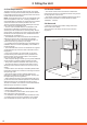
2 Siting the Unit The site for the unit must be dry and frost-free. The system installation must be planned in detail, with particular attention to the positioning of the fresh air and exhaust air ducts and to include sufficient sound insulation. NOTE: The temperature of the unit can be considerably lower than the temperature of the room, it is being installed in. To avoid undesirable accumulation of condensate, the circulation of fresh and exhaust air must be provided in the room.
3 Ducting, Controls and Condensate 3.3 Remote Control 3.1 Ducting connections Refer to diagram 3.3. • Atmosorb HRD 275: 4 x air duct connections ø 150 mm, or alternative ø 160 mm and ø 180 mm • Atmosorb HRD 350: 4 x air duct connections ø 180 mm, or alternative ø 200 mm • Control cable from the remote control to the unit is a 2-core cable, with cross-section 0,75 mm2. Maximum cable length 300m. The connection must comply with the current rules and regulations. 3.2 Bypass(Optional) 3.
4.1 Contents of Pack • Atmosorb unit • Digital remote control • Mounting set consisting of: • Fixing brackets 405 x 60 mm • Condensate drain trap Accessories (optional) • Bypass Atmosorb WALL MOUNTING BRACKET 14883 4 Installation • Filtersets H.E. F6 Ensure that the wall offers the appropriate load carrying capacity and that appropriate fixing are used to secure the unit. It is possible that the attached mounting set with the fixing screws and wall plug is not suitable for every wall.
4 Installation 4.4 Air Duct Connections Before executing the final connection check the air ducts are still clean. If necessary, clean the air ducts. Only then connect the air ducts to the unit. Connect the air ducts to the connections on top of the unit. NOTE: Air ducts must be tightly connected to the unit - use suitable accessories or sealing material. Insulation of the fresh air and outgoing air ducts must be diffusion resistant. The unit is equipped with a fixed front panel.
4 Installation - Bypass (Optional) IMPORTANT: Switch off the mains supply to the unit before starting to work. Improper electric installation may cause accidents. Therefore it is absolutely mandatory to have a competent person approved at the time by the Health and Safety Executive to complete the electrical installation. 14886 4.6 Mounting and Electrical Connection of the Bypass (optional) TEMPERATURE SENSOR NOTE: The bypass electrical connection must be completed before mounting.
Site the remote control on an inside wall at a height of about 1.5 m, were the controller is able to detect the circulating ambient air clearly and unimpeded from furniture, curtains or other external influences. The position should be selected so that neither air drafts from the door or the window nor heat sources such as radiators, TV or solar irradiation may directly influence the controller. A connection with the ventilation unit is established via a 2-core connection cable.
4 Installation - Controls 4.9 Establishment of Electrical Connection of the 3-stage Switch (optional) In addition to the standard control unit, you can also use a universal 3-stage switch, routed into X12 of the PCB, to control the ventilation unit. This must be potential-free (no voltage), see diagram 4.9. Connect as shown in diagram 4.10 to the clamps „0↓”, “D↑” and “H↑”.
Installation - Controls 4.12 Removal of cable insulation 4.10 Alarm Input (optional) The alarm input (connection „X 14“ on the board) is bridged when the unit is delivered. If the connection is undone with an external potential-free switching contact (break contact), both fans will be switched off. On the display of the remote control you will see the message “LOCK“. IMPORTANT: Disconnect from the mains electricity supply before starting to work on the unit.
5 Commissioning 5.1 Function checks Once all connections are correctly installed in accordance with the wiring scheme, check the functions of the remote control, the ventilation unit and the bypass. When doing so, note that the unit must not be started until all ventilation ducts are connected to the unit and the unit and all ductwork are completely sealed.
5 Commissioning Please refer to diagram 5.1 for control panel buttons and layout: Action press mode button for 10 secs Display AIR1 Meaning Set volume flow night 1st stage Atmosorb HRD 275 350 Default setting m3/h 80 105 Min m /h 50 70 Max m3/h AIR2 AIR2 3 Set volume flow for the non-programmed periods.
5 Commissioning * Setting will be required if the automatic switching from summer to winter time is to be activated. 5.5 Service/Diagnostics Level The service/diagnostics level should help the installer during the service. Keep the mode and prog buttons simultaneously pressed for about 3 seconds to reach the service/diagnostics level. The . display will show the symbols By pressing and holding the “mode” button you will return to the basic display.
5 Commissioning Action Display BYP ON Meaning Bypass switches to summer mode ALAR ON Alarm output is activated (contact closed).
NOTE: Replace the filters at least once a year or after maximum 2000 operating hours. If the filters are heavily soiled, they should be replaced at shorter intervals. A competent person approved at the time by the Health and Safety Executive in the area of the air pollution control, should carry out regular inspections. The first inpection should be performed 3 months after commissioning.
IMPORTANT: When removing and replacing the heat exchanger take care not to damage it. Take care not to damage the heat exchanger fins. Any damage will lead to premature wear in the system. Refer to section 4.5 and open the unit and remove the filters then the front panel. Hold the heat exchanger with both hands at the edges and without damaging the fins, carefully pull out the heat exchanger, see diagram 6.2.
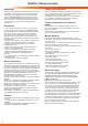
7 Fault Finding 7.1 Fault Finding The faults listed below may only be rectified by a competent person approved at the time by the Health and Safety Executive. The following checks should be performed before proceeding onto specific diagnostics: • Check the external electrical supply to the boiler is on and a supply of 230V is present at the ‘L’ and ‘N’ terminals on the installer interface, refer to section 11.4 for access and diagram 14.4.
7 Fault Finding Error Messages in the Remote Control Indication Check/ on the component display Cause Remedy Communication error between the PCB in the unit and the remote control. 230 V eBUS line laid parallel in pipe or cable channel. Alarm input "X 14" opened. Pull the mains plug and insert it again. If this does not help to eliminate the error, contact Glow-worm Customer Service.
Template: Start-up Measuring Report Fresh air flow Room Grille/louvre size 1. measurement 2nd measurement 3rd measurement Grille/louvre size 1.
Template: Filter Replacement Report Date Operating hours next change Name 27
Template: Hygiene Check Report Date 28 Operating hours opt.
Notes on Installation 29
Notes on Installation 30
0020063535-01 08.09 Because of our constant endeavour for improvement, details may vary slightly from those shown in these instructions. Glow-worm, Nottingham Road, Belper, Derbyshire. DE56 1JT www.high-efficiency.