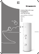
Instructions for use Installation and Servicing Solar Hot Water Cylinders/ Flurocyl2 200 250 300
Table of contents INT R O D U C T I O N 1 Instructions guidance.................................................................................................................... 3 1.1 1.2 1.3 1.4 1.5 2 Safety instructions and regulations................................................................................................ 3 2.1 2.2 2.3 2.4 2.5 3 Product documentation........................................................................................3 Associated documents ...............
Table of contents MA I N TE N AN CE 11 Inspection and maintenance........................................................................................................ 23 11.1 11.2 11.3 12 Recycling and disposal................................................................................................................ 25 12.1 12.2 13 -2- Cylinder disposal...............................................................................................25 Disposal of packaging........................
INTRODUCTION INTRODUCTION 1 Instructions guidance 1.1 Product documentation The instructions are an integral part of the appliance and must be handed to the user on completion of the installation in order to comply with the current regulation. • Carefully read the manual, to understand all the information to enable safe installation, use and servicing. No liability can be accepted in the event of damage for not complying with the guidance in this instruction manual. 1.
INTRODUCTION 2.2 General safety information 2.3.3 Avoiding damage caused by leaks Installation and adjustment as well as service, maintenance and repair must be carried out by a competent person approved at the time by the Health and Safety Executive and be in accordance with the relevant requirements of the Local Authority, Building Regulations, Building Regulations (Scotland), Building Regulations (Northern Ireland), and the bye-laws of the local Water Undertaking.
INTRODUCTION EN 806-1 3.1.2 Specifications for installations inside buildings conveying water for human consumption - Part 1: General You can set the hot water temperature and reheating times in the upper half of the cylinder on the controller.
read carefully before using 4 Operation a a Always make sure that there is clear access to the cylinder to enable the use of the hot water thermostat controller and the thermostat mixer. Risk of scalding and bursts due to inappropriate alterations! There is a risk of escaping steam, bursting, and damage to the system if you make any changes to the cylinder, control system, supply lines for water and power (if present), relief valve termination, or expansion relief valve for the cylinder water. 4.
read carefully before using 4.5 Fault finding Fault Remedy Fluid is dripping from the system? If possible, collect the fluid in a bucket and contact an engineer qualified to work on unvented systems. The controller issues a message telling me the sensor is faulty or there is a cable break? Contact an engineer qualified to work on unvented systems. The cylinder is not providing sufficient hot water? Check that the hot water temperature is set correctly on the controller (recommended value of approx.
technical data TECHNICAL DATA 6 Technical data Unit Flurocyl2 200 Flurocyl2 250 Flurocyl2 300 Total capacity l 200 250 300 Actual capacity l 209.4 254.4 297.2 Hot water capacity (upper coil) l 104.8 142 144.2 Hot water capacity (solar coil) l 203.3 246.1 271.1 Dedicated solar volume l 104.6 112.4 153.0 Maximum supply pressure to pressure reducing valve bar 12 Maximum operating pressure of cylinder bar 7 Maximum operating pressure of heating coil bar 3.
technical data Unit Flurocyl2 200 Flurocyl2 250 Flurocyl2 300 Primary heater flow 22mm compression joint Primar heater return 22mm compression joint Solar flow 22mm compression joint Solar return 22mm compression joint Primary heating circuit immersion sleeve size mm 8 Solar circuit immersion sleeve size mm 8 Electrical data Immersion heater (according to ENBS 60335) Length of immersion heater 2.
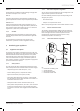
INSTALLATION INSTALLATION 7 Hydraulic and electrical schematics 4 3 8 230V 16A 5 6 10 9 11 D 7 12 7.1 13 14 2 7.2 15 E F 16 1 7.
INSTALLATION 4 3 8 5 6 9 230V 16A 10 D 7 11 12 EBUS 7.1 2 13 14 7.1 1 F E 15 7.2 C 16 17 19 G H A 18 B 9 230V~ PCSA PCSB/PC LEG/BYP R 230V 16A V3V 10 2 1 14 4 6 3A 13 15 12 2 230V~ CYL. DHW CH BUS DHW On Off On On + – NTC + – 7.1 8 2 1 N L N L N L L link C 3A 2 1 18 17 BUS 7.
INSTALLATION 8 Description of the components 8.1 Flurocyl2 solar cylinder Section 4.1 of this manual describes the Flurocyl2 solar cylinder in detail. 8.2 Solar pump safety thermostat 1 3 3 2 3 4 3 Fig. 4.
INSTALLATION 9 Cylinder installation 9.1 Cylinder device description 1 26 2 3 25 21 22 24 4 23 7 20 5 9 19 18 6 8 3 17 16 15 14 13 12 10 11 Key 1 Hot water connection 2 Expansion relief valve (one-way valve, 6.0 bar) 3 Pressure limiting valve (3.
INSTALLATION The Flurocyl2 solar cylinder is available in three sizes: 200, 250, and 300 litres. The containers are made from stainless steel with EPS insulation. The cylinder is supplied along with all required cold and hot water control devices and a 2-way motorised valve. The cylinder works with the pressure of the water supply line and does not need a cold water tank for its supply. The cylinder has hot and cold water connections with a diameter of 22 mm.
INSTALLATION 9.1.3 Safety devices The cylinder is delivered with all safety and control devices for the operation of the unvented domestic hot water supply: -- Temperature/pressure relief valve (90 °C, 7 bar) 9.2 Installation site Place the cylinder in a suitable location in the building, paying attention to the following: -- Pressure limiting valve (3.5 bar) with line strainer -- Expansion relief valve (one-way valve, 6.
INSTALLATION 9.3.2 Discharge requirements (G3 building regulations) SAFETY DEVICE (E.G. TEMPERATURE RELIEF VALVE METAL DISCHARGE PIPE FROM VENTIL) TEMPERATURE RELIEF VALVE 600 M TO TUNDISH M TUNDISH 300 MM MINIMUM DISCHARGE BELOW FIXED GRATING FIXED GRATING METAL DISCHARGE PIPE FROM TUNDISH WITH CONTINUOUS FALL From Sizing Table: Maximum resistance allowed for a straight length of 22 mm copper discharge pipe from a G1/2 temperature relief valve is: 9.0 m. Subtract the resistance for 4 No.
INSTALLATION 9.3.
INSTALLATION If you are using the cylinder with a gasfired boiler as per GB standards, you may have to install a suitable heating pump in the reheating circuit. 9.4.1 Installing the 2-way motorised valve In a thermal solar system, a hot water thermostat mixer must be installed as scald protection. The hot water thermostat mixer mixes the hot water from the cylinder with cold water to produce water with a maximum temperature of between 30 and 60 ºC as required.
INSTALLATION 9.6.1 Flurocyl2 hot water flow rates at 60 °C Risk of damage to the cylinder as a result of excess pressure! Excess pressure can cause the cylinder to burst. Make sure that the expansion relief valve outlet is not covered or closed. -- Mount the discharge pipe of the expansion relief valve with a constant slope to the outside. The discharge pipe must finish at a safe and visible point where there is no danger of it freezing up and where it poses no risk of injury to persons.
INSTALLATION 9.7 a e Electrical installation 9.7.4 Electrical connection of control components Improperly executed electrical connections can impair the operational safety of the unit. - Only a competent person approved at the time by the Health and Safety Executive may carry out the electrical installation. 1 9 10 2 3 Without earthing, life-threatening voltage can reach the piping and water draw-off points. 4 - Earth the cylinder.
INSTALLATION 9.7.5 Cylinder thermostat and thermal cut out (TCO) for the reheating circuit 1 14 9.7.7 The Glow-worm Flurocyl2 solar cylinders are fitted with an electric immersion at the factory. 9.7.
INSTALLATION 10 Commissioning 10.1 Filling the cylinder Use the draw-off points to bleed the cylinder and water pipes. Do not use the combined temperature/pressure relief valve of the cylinder or the pressure relief valve of the cold water safety assembly for bleeding, since foreign bodies can contaminate or damage the valves. • Make sure that the drain valve is closed. • Open all of the draw-off points in the cold and hot water pipes.
MAINTENANCE MAINTENANCE 11.2 Draining the cylinder • Close the cold water feed line. 11 Inspection and maintenance Glow-worm solar systems are designed to give a long trouble free life. In order to ensure this, an annual inspection of the solar circuit should be carried out by a competent person approved at the time by the Health and Safety executive . This would be carried out at the same time as the boiler and cylinder inspection and comprise mostly of visual checks.
MAINTENANCE 11.3 Fault diagnosis The following checks should be performed before proceeding onto specific diagnostics: 11.3.1 The faults described in this chapter should be carried out by an engineer qualified to work on unvented systems. Malfunction Cause Solution 1. The anti-siphon valve is blocked. 1. Check the position of the blue handle. 2. Check the anti-siphon valve for tightness (jammed cuttings, particles of dirt in the sealing face). 3.
MAINTENANCE Water flows out of the temperature/pressure relief valve (only during heating up). Only connection wiring diagram 6: The safety thermostat for the reheating circuit actuated at 80 ºC, thus causing the 2-way motorised valve to close the supply line to the cylinder. There is dirt on the valve seat of the temperature/pressure relief valve. Check the seat of the temperature/pressure relief valve and suppress the fault. The temperature control system for the gas-fired boiler is faulty.
MAINTENANCE 13 Customer service and manufacturer's warranty 13.1 Glow-worm service To ensure regular servicing, it is strongly recommended that arrangements are made for a Maintenance Agreement. Please contact Glow-worm Service (Tel. No. 01773 828100) for further details. 13.2 Glow-worm warranty Glow-worm provides a full parts and labour warranty for this appliance.
MAINTENANCE 14 Spare parts Key No. Part No.
MAINTENANCE MAINS PRESSURE HOT WATER STORAGE SYSTEM COMMISSIONING CHECKLIST This Commissioning Checklist is to be completed in full by the competent person who commissioned the storage system as a means of demonstrating compliance with the appropriate Building Regulations and then handed to the customer to keep for future reference. Failure to install and commission this equipment to the manufacturer’s instructions will invalidate the warranty but does not affect statutory rights.
INSTALLATION SERVICE RECORD It is recommended that your hot water system is serviced regularly and that the appropriate Service Record is completed. Service Provider Before completing the appropriate Service Record below, please ensure you have carried out the service as described in the manufacturer’s instructions.
Subject to engineering changes 0020115479_03 - 10/12 Glow-worm Nottingham Road, Belper, Derbyshire. DE56 1JT www.glow-worm.co.uk Because of our constant endeavour for improvement, details may vary slightly from those shown in these instructions.