
Manual


0020115479_03 - 10/12 - Glow-worm
- 10 -
N L 3
3
4 5 6 7 8 9
10
CH
C 2
C 2 C 2 1
N L L link
1 C
10 7
L
C 2
L link
230V~ PCSA PCSB/PC LEG/BYP V3VR
Bl Gr Or R R
N
L
R1
7
N L
230V
3A
3A
3A
3A
230V
16A
Bl
Gr
Or
Bl
Gr
Or
R
R
R
N
Load
230V
16A
15
1
1
3
2
8
19
18
20
17
7
6
6
4
5
14
11
12
12
9
10
10
9
16
13
A
B
G
H
F
E
15
8
19
18
2
14
11
4
16
13
C
D
7.1
7.1
7.3
7.3
7.2
7.2
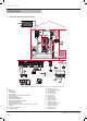
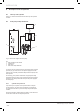
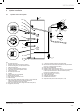
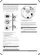
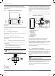
INSTALLATION
7 Hydraulic and electrical schematics
Key:
1 Boiler
2 Solar gain NTC
3 Solar collector
4 Collector NTC
5 Solar expansion vessel and protection vessels
6 Solar pump station
7 Domestic hot water cylinder
7.1 Cylinder dual thermostat
7.2 Immersion heater with thermal safety
7.3 Solar pump thermal cut-out
8 Additional terminal block
9 Electrical supply + protection (This must have it's own single
isolation)
10 Fluropro solar controller
11 CH time controller
12 Electrical switch
13 NTC sensor pocket (TAC 2)
14 Terminal block
15 Room thermostat
16 NTC sensor (TAC 2)
17 Heating circuit
18 DHW 2 port valve
19 CH 2 port valve
A Boiler circuit return
B Boiler circuit ow
C Cold water supply
D Domestic hot water outlet
E Cylinder circuit ow
F Cylinder circuit return
G Solar circuit return
H Solar circuit ow
INSTALLATION