
Manual


0020115479_03 - 10/12 - Glow-worm
- 12 -
8 Description of the components
8.1 Flurocyl
2
solar cylinder
Section 4.1 of this manual describes the Flurocyl
2
solar cylinder
in detail.
8.2 Solar pump safety thermostat
3
3
3
1
2
3
4
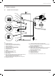
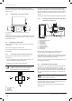
Fig. 4.1 Connection diagram for solar pump
Key
1 Solar controller or solar module
2 Terminal strip
3 Solar pump
4 Solar circuit safety thermostat
In order to meet the requirements for unvented hot water cylinder
systems (G3), you must connect the power supply for the solar
pump (3) via a manually resettable safety thermostat (TCO) in the
solar cylinder.
The Flurocyl
2
solar cylinder is tted with an appropriate safety
thermostat (4) at the factory. If the cylinder temperature is higher
than 80 °C, the safety thermostat interrupts the power supply to
the solar pump.
8.2.1 Cylinder frost protection
If you want to put a cylinder out of operation where it may be
at risk from frost, you must drain it completely. It is drained at
the cold water inlet with a T-piece with tap to be provided by the
installer.
Any heat exchangers not lled with solar uid in rooms which are
at risk of frost must also be completely drained.
INSTALLATION