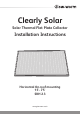
Clearly Solar Solar Thermal Flat Plate Collector Installation Instructions Horizontal On-roof mounting 15°- 75° SRH 2.3 www.glow-worm.co.
Guarantee Registration These Clearly Solar Flat Plate collectors come with a comprehensive manufacturer’s guarantee. Details of the guarantee, and the terms and conditions that apply can be found on the Guarantee registration card. We recommend you complete and return this as soon as possible. Customer Service: 01773 596510 Technical Helpline: 01773 828300 General and Sales enquiries: Tel.
These instructions must be handed to the user on completion of the installation.
WARNINGS Metal Parts This solar panel contains metal parts (components) and care should be taken when handling, with particular regard to edges. Risk of death from falls and falling objects Observe the national regulations for working at heights. Danger of burning and scalding In case of solar irradiation inside the units, solar panels can reach 200°C. Remove the sun protection film installed at the factory only after the solar energy system has been started up.
Statutory Requirements IMPORTANT Where no British Standards exists, materials and equipment should be fit for their purpose and of suitable quality and workmanship. The installation of this solar collector panel must be carried out by a competent person in accordance the rules in force in the countries of destination. Manufacturer’s instructions must not be taken as overriding statutory requirements.
1 Technical Specification Design Description The Clearly Solar, solar flat plate collector, collects the available solar radiation and transfers the heat through the solar fluid to be utilised by the system. It has been designed to compliment the complete range of Glow-worm solar system components. The kits are suitable for roof pitches between 15°- 75°, please choose from the table below.
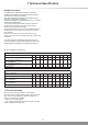
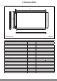
1075 79 2033 1978 79 80 1178 1233 14921 2 Technical Data Horizontal Collector Appliance designation Diagram 2.1 Unit. Absorber type Clearly Solar Serpentine Gross area 2 m 2.51 Aperture surface area m2 2.35 Absorber surface area m 2.33 Dimensions (L x W x H) mm 1233 x 2033 x 80 Weight (Dry) kg 38 2 Absorber Aluminium (vacuum coated) 0.5 x 1178 x 1978 Fluid content l 2.16 Copper pipe connection, flat-face Ø mm G 3/4" (DN16) Insulation thickness mm 40 Max.
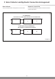
3 Solar Collector and Hydraulic Connection Arrangement Hydraulic Connections The recommended collector arrangements are shown below. It is recommended that the hydraulic connections should be made as shown below. 15045 Solar Collector 1-5 Collectors THE HYDRAULIC FLOW CAN BE DIAGONAL OR TOP AND BOTTOM 1 ... 4 5 6 and up to 10 max Collectors THE HYDRAULIC FLOW MUST BE DIAGONAL 1 ... 9 10 Diagram 3.
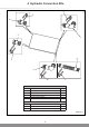
4 Hydraulic Connection Kits 15188 5 5 4 3 1 6 5 2 7 7 Easy fit hydraulic connection set - Kit No. 0020060207 Part Description Qty. 1 Upper supply (with probe) 1 2 Return (inlet) 1 3 Lower plug 1 4 Upper plug (with ventilation) 1 5 Securing clip 4 Easy fit hydraulic extension set - Kit No. 0020055175 Part Description Qty. 6 Pipe coupling 2 7 Securing clip 4 Diagram 4.
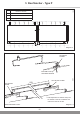
15186 5 Roof Anchor - Type P Distance in milimetres A 1233 B 200 - 300 C 1433 - 1633 74 A B C C B B B 15153 Diagram 5.1 SECURING SCREW COLLECTOR CLAMP 1233 COLLECTOR CLAMP *120 *120 15408 BOTTOM PLATE SECURING SCREW *120 *120 * Total adjustment of collector clamp can be 240mm to suit site conditions and reduce the need to cut tiles ROOF ANCHOR TYPE P Diagram 5.
5 Roof Anchor - Type P IMPORTANT ● With due regard to the complete weight of the solar collector system, (refer to technical data) ensure the roof rafters and battens are in good condition and have sufficient load carrying capacity and the battens are secure. 5.1 Fixing roof anchor type P Remove the roof tiles to expose the roof battens and rafters where required, please refer to diagram 5.1 and 5.2 for position of brackets. If required loosen the securing screw, see diagram 5.2.
6 Roof Anchor - Type S IMPORTANT ● With due regard to the complete weight of the solar collector system, (refer to technical data) ensure the roof rafters and battens are in good condition and have sufficient load carrying capacity and the battens are secure. 6.1 Roof anchor type S Refer to diagram 6.1. Remove the tiles where required, refer to diagram 5.1. The roof anchor must be secured to a rafter. Ensure that the roof anchor is secured with the screws supplied.
7 On-Roof Installation 15177 7.1 Collector installation Ensure the mounting brackets are level before securing, see diagram 7.1. Position the collector, protective side uppermost, on the mounting bracket and beneath the clamp, see diagram 7.2. NOTE: The design is symmetrical and does not have a top or bottom. MOUNTING BRACKET IMPORTANT: Do not remove the protective film until the system is to be commissioned Move the clamp into position ensuring the correct engagement of both clamps onto the collector.
Insert the pipe couplings up to the limit stop into the corresponding openings on the side of the collectors, see diagram 7.3. PIPE COUPLING SECURING CLIP Secure the pipe coupling with the securing clip 15168 7 On-Roof Installation Place the next collector on the lower mounting bracket. Slide the collector up to the first collector paying attention to the pipe couplings, see diagram 7.4. When fully inserted to the limit stops, ensure that the pipe couplings are secured with the securing clips.
7 On-Roof Installation 15181 With regards to the hydraulic system you have chosen, insert and secure the hydraulic connections, see diagrams 7.5 and 7.6. COLLECTOR SENSOR Connect the collector Flow and Return to the system circuit. Ensure that all of the following steps have been performed:- All the connections have been fixed with securing clips. - All hydraulic connections laid properly. - The collector sensor has been connected. - The collectors are connected to a lightning protection device.
0020080932-02 03.09 Because of our constant endeavour for improvement, details may vary slightly from those shown in these instructions. Glow-worm, Nottingham Road, Belper, Derbyshire.