Clearly Solar Installation and Servicing System Hydraulics including Solar Pump Station and Accessories www.glow-worm.co.
Guarantee Registration Thank you for installing a new Glow-worm solar system. Glow-worm products are manufactured to the very highest standard so we are pleased to offer our customers a Comprehensive Guarantee. This product is guaranteed for 24 months from the date of installation or 30 months from the date of manufacture, whichever is the shorter, for parts and labour.
These instructions consist of, Installation, Servicing, Fault Finding. The instructions are an integral part of the product and must be handed to the user on completion of the installation.
WARNINGS SAFETY The system must be installed by a competent person, who is responsible for adhering to the existing standards and regulations. ALTERATIONS Under no circumstances should you ever attempt to make alterations to these components or any other part of the system SEALED COMPONENTS Under no circumstances must the user interfere with or adjust sealed parts.
Statutory Requirements IMPORTANT Collectors and collector assembly Where no British Standards exists, materials and equipment should be fit for their purpose and of suitable quality and workmanship. ENV 1991-2-4 Eurocode 1 – Basis of design and actions on structures - Part 2–4: Actions on structures - Wind actions Solar cylinder and cylinder installation The installation of this product must be carried out by a competent person in accordance the rules in force in the countries of destination.
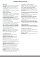
Notes on the Documentation Notes on the documentation Other applicable documents Your solar system is a quality product from Glow-worm. Collector installation instructions. This manual covers the solar system, excluding the cylinder and provides you with information on installation, commissioning, maintenance and fault finding. It is supplemented by the installation instructions of the individual components. System hydraulic installation instructions.
1 System Specifications 1.1 Intended use The solar system is used for the solar-supported supply of DHW. Any other use is considered to be improper. The manufacturer / supplier is not liable for any resulting damage. The user alone bears the risk. Intended use includes the observance of the system description and all other applicable documents, as well as adherence to the maintenance and inspection conditions.
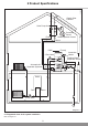
14162 2 Product Specifications Clearly Solar Collector Solar Pump Unit Flow DHW 2 Port Valve M Protection Vessel Solar Expansion Vessel Return Flurocyl Immersion Heater Drinking Water Expansion Vessel Automatic Air Separator System Boiler Flow Return M 2 Port Valve Diagram 2.1 2.1 Diagramatic view of the system installation Refer to diagram 2.
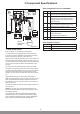
3 Component Specifications 250 2 120 6 Ø 22 Solar Pump Station part no. 0020054961 14829 7 5 Ø 22 3 358 1 Ø 22 Ø 22 Ø 22 Ø 22 4 SOLAR EXPANSION VESSEL CONTAINER Item Qty.
3 Component Specifications 3.2 Solar expansion vessel 3.3 Thermal cut out of the solar pump The solar expansion vessel, is used to equalise the pressure while the pressure relief valve blows off the solar fluid into the collecting container via the pressure release pipe if the operating pressure of 6 bar is exceeded. The solar pump must be protected by its own thermal cut out (TCO) which must be mounted on the solar cylinder (preassembled at the factory on the Glow-worm Flurocyl cylinder).
4 Installation 14172 Make sure that you have all the components required, see diagram 4.1, 4.2 and tables 4.1 and 4.2, below. 4.1 Recommended installation sequence Assuming that the cylinder and collectors are fitted with the exception of the solar system hydraulics and wiring, it is recommended that the solar pump station is now fitted followed by the solar circuit pipework. 1 The cylinder and collectors must be installed in accordance with the separate installation instructions.
14213 4 Installation SOLAR COLLECTOR THERMOSTAT MIXER SOLAR COLLECTOR CIRCUIT PUMP PUMP HOT WATER CONNECTION LEGIONNELLA LOOP (optional) TEMPERATURE AND PRESSURE RELIEF VALVE (95 °C, 7 BAR) BOILER EXPANSION VESSEL FLOW RETURN MOTORISED 2 PORT VALVE EXPANSION RELIEF VALVE (6.0 BAR) PRESSURE LIMITING VALVE (3.5 BAR) WITH LINE STRAINER FLOW MOTORISED 2 PORT VALVE COLD WATER SUPPLY TUNDISH RETURN AUTO AIR SEPARATOR FLUROCYL DRAIN VALVE Diagram 4.
4 Installation 14212 Collector arrays setup for East / West orientation N W E S SOLAR COLLECTOR SOLAR COLLECTOR SOLAR COLLECTOR CIRCUIT PUMP THERMOSTAT MIXER HOT WATER CONNECTION BOILER PUMP LEGIONNELLA LOOP (optional) TEMPERATURE AND PRESSURE RELIEF VALVE (95 °C, 7 BAR) EXPANSION VESSEL FLOW RETURN MOTORISED 2 PORT VALVE EXPANSION RELIEF VALVE (6.0 BAR) PRESSURE LIMITING VALVE (3.
4 Installation 4.2 Fitting the solar pump station (wall-mounted installation) IMPORTANT: Use hard solder only, soft solder is NOT suitable. Do not use any plastic pipes. Fit the wall bracket and the pump station flow and return assemblies. Flexible stainless steel pipes supplied by Glow-worm or copper pipes should be used for the solar circuit. Secure the assemblies in the wall bracket using the two Cclips. Put them onto the flow and return assemblies below the wall bracket.
4 Installation IMPORTANT: Ensure the cylinder pipes are connected correctly - the pump station return assembly includes the pump. The system must be bled whenever it is filled or subjected to maintenance. Bleeding is performed constantly by means of the automatic air separator system as long as the solar pump is in operation. 4.5 Automatic air separator Fit the protection vessel as shown in diagram 4.6. Air in the system impairs the efficiency of the solar system considerably.
5 Commissioning EXAMPLE: The installed (net) collector surface area for Clearly Solar collectors is 2.35 m2. Multiplied with the value for the specific flow rate of 0.66 l/m2 • min, it results in a calculated flow rate, which should be indicated by the flow rate meter, see diagram 5.1. You must adhere to the following procedure for the commissioning of the total system: Use only Glow-worm solar fluid (item no. 0020054968) for pressure tests and for flushing and filling the solar circuit.
5 Commissioning 5.3 Commissioning checklist Fill in the commissioning checklist, refer to section 6. 5.4 Benchmark GB: It is a requirement that the “Benchmark” Installation, Commissioning and Service Record is completed and left with the user. This is supplied with the Glow-worm ‘Flurocyl’ range of cylinders. IE: it is necessary to complete a “Declaration of Conformity” to indicate compliance to I.S.813. An example of this is given in the current edition of I.S.813. 5.
6 Commissioning Checklist 1. Assembly O.K. Remarks O.K. Remarks O.K. Remarks O.K.
6 Commissioning Data Information Unit Value/Detail Benchmark no. Registration no. Basic acceptances Number of persons Additional hot water equipment Washing machine, dishwasher etc.
6 Commissioning Data Information Unit Frost protection set to Density of solar fluid > 1.05 g/cm3 Value/Detail Controller settings Installed controller(s)/timer(s) Manufacturer Reheating with boiler starts at (TSP1 min. see installation manual of solar control)? °C Switch-on temperature difference: Kelvin Switch-off temperature difference: Kelvin Other settings Important activated functions Name of the installer (in block letters) Corgi ID No.
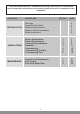
7 Inspection and Maintenance The operational reliability of the solar system may be impaired, resulting in damge to property or personal injury, if the inspections and maintenance work are not carried out. The main maintenance work on the solar system and the corresponding maintenance intervals are specified in table 7.1.
8 Fault Finding The following tables provide information on possible malfunctions during the operation of the solar system as well as their cause and remedy. All work on the Glow-worm solar system (installation, maintenance, repairs etc.) may be performed only by approved specialists. IMPORTANT: Risk of serious injury or death! Never try to correct faults in the solar system yourself. Bear in mind that you risk death or serious injury if the work is performed incorrectly.
8 Fault Finding Malfunction Cause Remedy The pressure gauge indicates a drop in pressure. A drop in pressure is normal shortly after filling the system, since air still escapes from the system. If a pressure drop occurs again later on, the cause may be an air bubble, which has been subsequently released.Furthermore there are fluctuations to the pressure in normal operation mode between 0.2 to 0.3 bar, depending on the system temperature.
8 Fault Finding Malfunction Cause Remedy Only cold or lukewarm water comes out of the taps. 1. Cold and hot water connections on the cylinder have been mixed up. Turn off the cold water supply, then let water flow out via the hot water connection. Only a few litres of water flow out if the connection is laid correctly. The inlet of the hot water draw-off pipe then rests in the air space; no further emptying is possible.
9 Solar Fluid Safety Data 10.1 Safety data sheet 6 Measures to be taken if substances are released accidentally 1 Substance/Formulation and company name Individual-related measures: No particular measures required. Information on the product: Trade name of the Glow-worm solar fluid (item no. 0020054968) Environmental measures: The product may not be discharged into waters without pretreatment (biological sewage plant). 2 Composition/Information on components Chemical properties Watery solution of 1.
9 Solar Fluid Safety Data 10 Stability and reactivity 15 Regulations Substances to be avoided: Strong oxidants Labelling in accordance with EC directives/national regulations: No labelling obligation Dangerous reactions: No dangerous reactions if the storage and handling regulations/notes are observed Other regulations: water hazard class (Germany, Appendix 4 of the VwVwS (administrative regulation on water-pollutant substances) from 17.05.
Glow-worm, Nottingham Road, Belper, Derbyshire. DE56 1JT Because of our constant endeavour for improvement, details may vary slightly from those shown in these instructions. 28 0020055003-04 02.