
Manual

14
4 Installation
IMPORTANT: Use hard solder only, soft solder is NOT
suitable.
Do not use any plastic pipes.
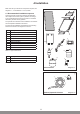
Flexible stainless steel pipes supplied by Glow-worm or
copper pipes should be used for the solar circuit.
Optional Glow-worm exible pipes for the connection of the
collectors to the solar pump unit.
0020054994: 2 in 1 exible pipe DN 16 x 15 m
0020054964: single exible pipe DN 16 x 15 m
Two single exible pipes DN 16 x 15 m are available as part
of the Glow-worm optional pipework kit. Instructions for the
connection of these exible pipes can be found in separate
installation instructions.
Due to the occasionally high temperatures of the solar uid,
plastic pipes must not be used for the solar circuit. Copper
pipes must be joined using hard soldering or compression
ttings. Soft soldering is NOT suitable.
Teon tape can be used on pipework below the Solar Pump
Station.
IMPORTANT: Earth the solar circuit!
The solar pipework must be earthed in accordance with the
requirements of BS 7671 IEE Wiring Regulations. Wiring
protection should be provided if there is high risk of lightning
strikes. The electronics in the solar system, heating system or
in the house could otherwise be destroyed if they were to be
hit by lightning. Connect the collectors to an existing lightning
protection on the house.
IMPORTANT: Risk of damage to the collectors due to
excessive pressure. The installation of a motorised 2 port
valve in the pipes of the solar system is not allowed, since the
safety devices in the solar circuit could be overridden by it.
The right selection of the pipe diameters plays a signicant
role in terms of maximum efciency of the solar system.
To keep the pressure loss in the solar circuit to a minimum,
the ow velocity in the copper pipe should not be higher than
1.5 m/s.
A nominal ow rate of 0.66 l/min per net m
2
collector surface is
required by the collectors to achieve optimum heat transfer.
Another decisive criteria for the optimum operation of your
solar system is the speed of the solar pump. The pump must
be able to deliver more than the nominal ow rate at the
specied operating pressure. The selection of the required
pump speed depends on the installed system. Reference
value for the pump selection can be found in section 5.2.
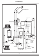
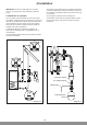
Connections to solar pump station
IMPORTANT: An air separator is required - refer to diagram
4.5.
Using the compression ttings supplied with the pump station,
connect the pump station ‘ow’ assembly to the collector ow
pipe and the pump station ‘return’ assembly to the collector
return pipe. IMPORTANT: ensure the collector pipes are
connected correctly - the pump station ‘return’ assembly
includes the pump.
Use the ttings included to connect to 22mm copper pipes.
Again using the compression ttings supplied with the pump
station, connect the pump station ‘ow’ assembly to the
cylinder ‘solar circuit ow’ connection then the pump station
‘return’ assembly to the cylinder ‘solar circuit return’.
4.2 Fitting the solar pump station
(wall-mounted installation)
Fit the wall bracket and the pump station ow and return
assemblies.
Secure the assemblies in the wall bracket using the two C-
clips. Put them onto the ow and return assemblies below the
wall bracket.
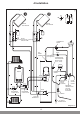
4.3 Pressure relief valve and expansion vessel
Fit the pressure relief valve assembly to the connection nozzle
in the pump station return tube assembly.
IMPORTANT: Loss of solar uid! Install a discharge pipe from
the pressure relief valve outlet to a container to ensure that
any hot solar uid escaping from the system is contained.
The solar uid container is intended as a collecting container
when the system is lled and the container is empty. Connect
a discharge pipe from the relief valve outlet to the intended
location for the container.
Mount the expansion vessel wall bracket using screws and
plugs. Screw the ange and the expansion vessel to the wall
bracket.
The expansion vessel must be mounted vertically and the ow
from the system must enter the vessel from the top. To avoid
accidental spillage or access by children to the uid, best
practice is to take the discharge pipe right to the bottom of
(but not touching) the container.
The empty solar uid container is recommended, as re-
using it helps to reduce landll, the contents of the container
are visible (you must be able to see if the safety valve has
discharged) and offers a practical solution. However, if
preferred, an alternative vessel may be used, provided it is
of adequate size, the contents are visible and it is not fully
sealed.
4.4 Notes on the solar circuit pipework
When installing solar circuit pipework between the collector
array and the cylinder, carefully consider the location of
the pump station and the requirement for an automatic air
separator. The Glow-worm solar system is a closed hydraulic
system in which heat can only be transferred to the cylinder
by means of special heat transfer uid in the solar system.
Observe the following points to ensure perfect operation with
maximum energy utilisation:
Bleed the system completely during commissioning and
servicing since air in the system has a considerable effect on
the efciency.
The pipe diameters should not be too large, otherwise the
the ow in the solar system will slow down, reducing the
efciency.
Lay all system components in such a way to ensure an even
ow at the required nominal ow rate.
Provide sufcient thermal insulation of the pipes to prevent
excessive heat loss. The insulation must withstand
temperatures up to 150°C. Select weather and UV resistant
insulation which is “bird peck proof“ especially for pipes laid
outside.
When using compression ttings, you must consult the
manufacturer of these ttings to check their suitability for solar
systems.
Use compression ttings only if temperatures of up to 200°C
are allowed by the manufacturer.