
Manual

16
5 Commissioning
You must adhere to the following procedure for the
commissioning of the total system:
Use only Glow-worm solar uid (item no. 0020054968) for
pressure tests and for ushing and lling the solar circuit.
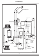
5.1 Flushing and filling the solar circuit
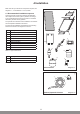
Glow-worm recommends using the Glow-worm lling pump,
part no. 0020054986, to ush and ll the solar circuit. Observe
the separate user manual when using the Glow-worm lling
pump.
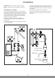
Expansion vessel admission pressure
During the commissioning, the gas side admission pressure
p
v
of the expansion vessel must be adjusted to the equipment
height whilst disconnected. The static pressure p
stat
corresponds, to a certain extent, to the static height h between
the collector array and the expansion vessel.
10m static height correspond to approx. 1 bar.
p
v
= p
stat
= h x 0.1 but not less than 1.5 bar.
NOTE: A deviation from the optimum admission or lling
pressure always results in a reduction of the expansion
vessel's effective volume. This can cause operational
malfunctions.
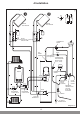
Flushing is performed from the solar pump station to the
cylinder via the collector.
A self-priming pump with a pressure of 2 to 3 bar is required
to ll the solar circuit.
Collector circuit lling pressure
The lling pressure Pa should be approx. 0.5 bar over the
static pressure Pstat.
Pa = h x 0.1 + 0.5 bar but not less than 2 bar.
5.2 Setting the flow rate / pump speed
The 3-speed circulating pump can be ne-tuned to adjust the
ow rate to the collector's performance.
NOTE: We recommend a value of 0.66 l/min per m2 collector
surface area.
This is how to do it:
Use Table 5.1 to calculate the ow rate to be set by
multiplying the installed collector surface area with the value
of 0.66 l/m2 • min.
Set the pump speed to roughly set the ow rate as follows:-
Let the pump run rst at the lowest speed (minimum power
consumption).
Check whether the calculated value is achieved on the ow
rate meter.
0,5
1
2
3
0,5
1
2
3
4
5
6
4
5
6
L/min
L/min
1,1 l/min
Adjustment
Valve
Flow Rate
Display
14168
Diagram 5.1
EXAMPLE: The installed (net) collector surface area for
Clearly Solar collectors is 2.35 m
2
. Multiplied with the value
for the specic ow rate of 0.66 l/m
2
• min, it results in a
calculated ow rate, which should be indicated by the ow
rate meter, see diagram 5.1.
Select the next pump speed if the calculated ow rate is not
achieved on the ow rate meter. Switch to a lower speed if it
is exceeded. If the ow rate cannot be achieved even at the
highest pump speed, check whether it is possible to use fewer
collectors in series reverting to a combination of series and
parallel connections (eg 2 collectors in series in parallel with
an additional 2 collectors in series).
Use an Allen key to nely adjust the ow rate at the
adjustment valve, see diagram 5.1.
The adjusted ow rate can be viewed on the display, see
diagram 5.1.
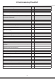
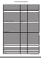
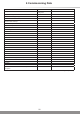
Table 5.1 provides reference values for possible pump speeds
depending on the collector connection and pipe length and
cross-section.
The ow rate can be used to calculate and display the
gain. To make an accurate calculation, the ow rate must
be entered into the Fluropro solar control. You can nd
further information in the separate system wiring instructions
including the Fluropro solar control.
The pump speed is used to achieve a particular ow rate
in the collector array. The nal ow rate should not be
signicantly above or below the calculated value. Up to 10%
lower solar gain or unnecessarily high power consumption of
the pump could occur.
Clearly Solar, solar collector panel Flow rate
Minimum cross-section of the copper pipe in the
solar circuit at a total pipe length of:
Number in series l/min 20m 50m
1 1 1.55 15 15
2 2 3.1 15 15
3 3 4.65 15 15
Pump speed: Minimum (speed 1) Maximum (speed 3)
Table 5.1 Layout of pipe cross-section and pump speed depending on the collector connection