221564F.11.00 Instructions for Use Installation and Servicing To b e l e f t w i t h t h e u s e r G.C. No. 47-047-01 6548 Energysaver Combi 80 100 G.C. No. 47-047-02 Condensing Combination Boiler Energysaver Combi This is a Cat I2H Appliance Reference in these instructions to British Standards and Statutory Regulations/Requirements apply only to the United Kingdom. For Ireland the rules in force must be used.
Contents CONTENTS INSTRUCTIONS FOR USE INSTALLATION INSTRUCTIONS SERVICING INSTRUCTIONS DESCRIPTION SECTION Introduction Operating the Boiler Clock Setting PAGE No. 3 3 5 General Information Boiler Position Flue Location and Ventilation Heating System Domestic Hot Water System Installation Preparation Flue Preparation Boiler Fixing Gas, Water and Condensate Conns.
Important Information Protective clothing is not required when handling these articles, but we recommend you follow the normal hygiene rules of not smoking, eating or drinking in the work area and always wash your hands before eating or drinking. Normal handling should not cause discomfort, but follow normal good hygiene and wash your hands before eating, drinking or going to the lavatory. If you do suffer irritation to the eyes or severe irritation to the skin seek medical attention.
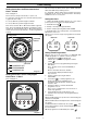
Operating the Boiler If the mains electricity and gas are to be turned off for any long periods during severe weather, it is recommended that the whole system, including the combination boiler, should be drained to avoid the risk of freezing. 6. Set clock/timer (if fitted) and any remote controls as required. 7. If the display is flashing, press the 'reset' button, shown on diagram 1. 8. The boiler should now operate.
Clock Setting This is a 24 hour clock/timer, that is 1pm is '13:00', and has 8 “ON” and 8 “OFF” daily switching actions. Setting Instructions for Electro/mechanical Clock - if fitted This clock has a twenty four hour dial, i.e. 1pm is '13'. It is fitted with a lithium battery back up which protects the programme in the event of an electrical failure. The battery should have a life of several years. To set the time, turn the whole face clockwise until the pointer is against the time of day.
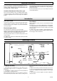
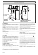
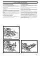
1 General Information 6513 145 520 373 208 101 118 33 CONDENSATE DRAIN (ES80)890 (ES100)985 Condensate Drain Connection INSIDE WALL FIXING FACE CL BOILER 145 SPIGOT 145 REFER TO THE WALL TEMPLATE FOR PIPE DIMENSIONS Diagram 1.1 1.1 Installation Isolation should be by a double pole switched fused spur box, with a minimum gap of 3mm for both poles. The fused spur box should be readily accessible and preferably adjacent to the appliance. It should be identified as to its use.
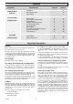
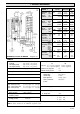
1 General Information 6499 TABLE 1 C.H. Max NOMINAL kW HEAT Btu/h INPUT kW GROSS Btu/h 27.5 93,830 32.5 110,890 8.0 27,266 10.2 34,802 24.5 83,600 28.8 98,266 24.5 83,600 28.8 98,266 6.8 23,200 8.9 30,367 25.5 87,000 30.5 104,066 25.5 87,000 30.5 104,066 7.7 26,170 9.8 33,438 -4.5 -1.8 -0.5 -0.2 80 -4.8 -1.92 9.2-9.6 -4.8 -1.92 9.2-9.6 -0.5 -0.2 9.2-9.6 100 9.0-9.4 9.2-9.6 9.0-9.4 9.2-9.6 9.0-9.4 9.2-9.6 9.0-9.4 2.6 91.8 9.0-9.4 2.6 91.8 9.0-9.4 0.7 24.7 2.9 102.4 0.9 31.
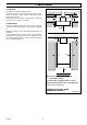
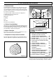
2 Boiler Position 6498 2.1 Location The boiler is not suitable for fitting outdoors. Any electrical switch or boiler control using mains electricity must be positioned so that it cannot be touched by a person using a bath or shower. 5 The boiler must be mounted on a flat wall which is sufficiently robust to take its weight, refer to Table 2. 2.2 Clearances * * The boiler should be positioned so that at least the minimum operational and servicing clearances are provided, see diagram 2.1.
3 Flue Location and Ventilation 3.1 Flue Position and Length 3.3 Terminal Position There are several flueing options available for the Energysaver Combi, e.g. horizontal, vertical and twin flue. The minimum acceptable siting dimensions for the terminal from obstructions, other terminals and ventilation openings are shown in diagram 3.4. The standard horizontal flue is fitted onto the top of the boiler using the flue elbow.
3 Flue Location and Ventilation 3.4 Terminal Guard A terminal guard is required if persons could come into contact with the terminal or the terminal could be subject to damage. If a terminal guard is required, it must be positioned to provide minimum of 50mm clearance from any part of the terminal and be central over the terminal. C A The guard should be similar to that shown in diagram 3.5. B,C B,C G A Tower Flue Components Morley Rd.
4 Heating System 4.1 General 4.4 Bypass The boiler is for use in sealed water systems only. The boiler is fitted with a manual bypass, see diagram 4.3. This valve may be adjusted by the installer if necessary to ensure at least 400 litres/hr for ES80 and 470 litres/hr for ES100 flow through the boiler. The boiler is supplied with the bypass open by approximately half a turn and is closed by turning the white screw clockwise.
4 Heating System 4.6 Water Treatment 4.7 Draining Tap For optimum performance after installation, the boiler and its associated central heating system should be flushed in accordance with BS7593:1992 using a cleanser such as Sentinel X300 or X400, or Fernox Superfloc. A draining tap must be provided at the lowest points of the system, which will allow the entire system to be drained. The flow and return isolation valves are provided with drain points for boiler heat exchanger drainage, see diagram 8.1.
5 Domestic Hot Water System 5.1 Water Pressure 5.4 Mixing Valve The maximum working pressure of the domestic hot water circuit is 8 bar. There is a domestic hot water mixing valve fitted to the boiler base and this is factory set at approximately 60OC. This can be adjusted if necessary to supply a lower temperature. Turn the 5mm adjuster anticlockwise to reduce the temperature, see diagram 14.7. The domestic hot water temperature can also be adjusted, see section 11.8.
6 Installation Preparation Extended flue length The wall mounting jig can now be pre-plumbed without the boiler being mounted if necessary. All water, gas and electric connections are on the wall mounting jig with the exception of the condense drain, the position of which is shown on the wall template for pre plumbing purposes. See sections 9 and 10 for details of gas, water, condensate and electrical connections. Standard flue length 2.5˚ Inclined 6525 6.5 Pre Plumbing 208 900 Horizontal 6.
7 Flue Preparation 7.1 Flue Length For a rear flue, measure the distance from the outside wall face to the boiler mounting wall. Check that the flue length will be suitable, see diagram 3.1 for a standard flue system. 6505 X + 196 ( AIR DUCT ASSEMBLY) Note: All dimensions are in mm. BOILER MOUNTING WALL X For a side flue, measure the distance from the outside wall face to the flue outlet centre line of the boiler. Check that the flue length will be suitable, see diagram 3.
7 Flue Preparation Fit flue elbow ‘G’ to air pipe ‘B’ and flue duct ‘A’. A small amount of lubricant can be applied to the rubber seals in the elbow to facilitate this. 7.6 Flue Attachment To Boiler Refer to section 8 and fix the boiler in position prior to completing the flue installation. Secure the rubber dome ‘J’ to the top of the boiler with securing ring ‘H’ and screws provided. Pull off the wire clip on the flue adaptor pipe inside the boiler, see diagram 7.5.
8 Boiler Fixing Boiler Fixing Having previously secured the wall mounting jig and hanging bracket to the wall, lift the boiler into position in the following manner. To assist in the lifting of the boiler, remove the casing door. DRAIN POINT DOMESTIC WATER VALVES DRAIN POINT GAS SERVICE COCK Lean the top of the boiler slightly to the wall and position just above the hanging bracket. Allow the boiler to slowly move downwards until engaged in the hanging bracket.
9 Gas, Water, and Condensate Connections 5238 Make sure that the drain points on the isolating valves are positioning towards the front of the boiler, also that the drain and operating screw heads are accessible. 9.3 Safety Valve Discharge WARNING: The pipe from the safety valve must not discharge above an entrance, window or any type of public access area. CAP A short discharge pipe is supplied loose in the wall mounting pack. This must be extended, using not less than 15mm o.d.
10 Electrical Connections 10.2 Heating System Controls 10.4 Frost Thermostat WARNING: Mains electricity must not be connected to the black auxiliary control plug. This boiler has its own frost protection device to protect the boiler. Additional frost protection may be required for exposed pipework. If required, connect a single pole frost thermostat to the appropriate terminals of the black electrical connector plug as shown in diagram 10.3.
11 Commissioning Please ensure the “Benchmark” logbook is completed and left with the user. Press the ‘Reset’ button and the boiler will restart, see diagram 1 in Instructions for Use 11.1 Filling Domestic Water Circuit Flashing digits indicate a fault. Refer to fault finding if any fault persists, see section 13. Fully open any valves in the domestic water supply to the boiler. After the burner has lit, the boiler will initially heat up the domestic hot water cylinder.
11 Commissioning 6532 PROTECTIVE CAP CONNECTIONS 6533 ELECTRICAL BRASS LUGS ELECTRICAL CONNECTIONS PRESSURE TEST POINT CONTROL DOOR Diagram 11.2 Repeated pressing of the 'Mode' button gives the display sequence shown in diagram 11.4. Diagram 11.3 Temperature Options There are four domestic hot water and four central heating options to choose from. These options are shown on the digital display by repeated pressing of the ‘Mode’ button. The sequence is shown in diagram 11.4.
11 Commissioning Control Options Minimum Input Lock There are two control options available: Normal mode and Holiday mode, see diagram 11.4. This function allows the service engineer to lock the appliance into delivering minimum heat input to enable accurate combustion analysis. Normal mode uses the domestic hot water and central heating temperatures selected. Maximum Input Lock Holiday mode shuts down the domestic hot water and central heating.
NOTE:- The SYMBOL 6563 11 Commissioning (flashing decimal point) indicates the selected options BOILER TEMPERATURE (Decimal Point illuminated means boiler is firing) to Press Mode - 65 O C Press Mode - 55 O C Press Mode - For use with a supplementary hot water cylinder Press Mode - OFF Press Mode - 55 O C with adaptive control Press Mode - 70 O C with adaptive control Press Mode - 85 O C Press Mode - 85 C with continuous pump operation Press Mode - Normal mode Domestic hot water optio
The operating sequence of the appliance can be checked against the following two tables. DOMESTIC HOT WATER SEQUENCE TABLE 11.13 Pump Exercise Program DISPLAY (Operating function) CENTRAL HEATING SEQUENCE TABLE DISPLAY (Operating function) 6572 After a power cut or every 24 hour in holiday mode the three way valve will switch and the pump will run for one minute to prevent ACTION No demand. Create demand by turning on a hot water tap. Pump and fan start. No demand. Fan running up to speed.
12 Servicing 12.1 General 12.4 Spark Electrode To ensure the continued efficient and safe operation of the boiler it is recommended that it is checked and serviced at regular intervals. The frequency of servicing will depend upon the particular installation and usage, but in general, once a year should be sufficient. Remove the spark plug lead and two securing screws. Withdraw the spark electrode and viewing window from the combustion chamber, see diagram12.3. Inspect the tips for damage.
6545 6560 12 Servicing SECURING PLATE SPARK ELECTRODE SECURING SCREW (2 OFF) WING NUT SPARK PLUG LEAD Diagram 12.3 SECURING PLATE 6526 LEDGE Ensure the securing plate forks are supported on the ledge. Fan removed for clarity Diagram 12.6 6550 SECURING PLATE ELECTRODE GASKET SPARK GAP 3.5 + 0.5mm FAN SPARK ELECTRODE SECURING SCREW (2 OFF) 6552 FAN INLET FLANGE Diagram 12.7 6544 Diagram 12.4 SPARK ELECTRODE FAN THERMOSTATIC MIXER VALVE WATER INLET FILTER Diagram 12.
12 Servicing 12.6 Combustion Check. 12.8 Casing Panel Removal Connect a CO2 combustion analyser to the test point on the flue elbow if fitted, or alternatively to the sample point at the base of the flue outlet pipe inside the boiler casing, see diagram 12.1. During major servicing or replacement of parts it may be necessary to remove the boiler side panels to gain access. Turn on the gas isolation valve, see diagram 8.1.
12 Servicing 6534 12.11 Heat Exchanger - Major Servicing Refer to Fault Finding sections 13.1, (fault code 0 and 8 .) and 13.4 before carrying out a major service of the heat exchanger. TOP PANEL NUTS (6 OFF) If it is suspected that the heat exchanger has become partially blocked internally, proceed as follows. Remove the burner and fan as described in section 12.3. Remove the wire clip from the internal flue adaptor, see diagram 7.5.
6576 13 Fault Finding KEY Red Black Blue Brown Green Yellow Green/Yellow White Orange Grey r b bl br gr y g/y wh or gy LOW VOLTAGE PLUG Room thermostat Clock/timer Frost thermostat FLAME IGNITION AND ONISATION ELECTRODE 230V/50Hz MAINS PLUG P.
13 Fault Finding 13.1 Digital Display - Fault Codes If the fault code is not removed then an internal fault has occurred in the Automatic Control Module. If a fault has occurred during operation of the boiler the display will start flashing. Refer to section 14.4 and replace the module. Fault Code = 2 and 4 . Two numbers will alternate to show what type of fault has occurred. The second number has a decimal point after it.
13 Fault Finding If after checking all previous points the error code is still present, this suggests that the heat exchanger has become partially blocked. See section 12.11 for major service of heat exchanger. 13.3 Thermistor Characteristics All three thermistors used on the boiler can be checked for accuracy against the chart below if their performance is suspect. Fault Code = 2 and 8 . The fan is stationary or there is no fan speed signal.
14 Replacement of Parts 14.1 General Remove the gas pipe. Replacement of parts must be carried out by a competent person. Remove the domestic hot water pipe. Before replacing any parts the boiler should be isolated from the mains electric supply and the gas should be turned off at the service cock on the boiler, see diagram 8.1. Remove the pump. See section 14.14. Unless stated otherwise parts are replaced in the reverse order to removal. Fit the replacement valve and replace pipework.
14 Replacement of Parts 6546 14.11 Gas Valve Remove the injector pipe as described in section 12.3. Remove the gas injector as described in section 14.10. POCKET Remove the electrical connections from the gas valve, see diagram 11.2. Undo the gas pipe nut from beneath the base panel. Undo and remove the two securing screws from beneath the base panel. DOMESTIC HOT WATER THERMISTOR Remove the gas valve.
14 Replacement of Parts Refill, vent and pressurise the boiler. 6567 ELECTRICAL CONNECTION Check for leaks. (2 OFF) 14.19 Thermostatic Mixer Valve Refer to section 12.10 and drain the boiler hot water circuit. From below the boiler base plate, remove the gas pipe and remove both cold and hot water pipes from the thermostatic mixer valve. THERMISTOR CLIP From above the boiler base plate remove the three way valve head. See section 14.5. Undo both hot and cold water connections to the cylinder.
14 Replacement of Parts 6540 The right hand casing panels should be removed as described in section 12.8. Remove the gas valve as described in section 14.11. Remove the fan and burner as described in section 12.3. Remove the central heating flow thermistor as described in section 14.8. Remove the ignition electrode as described in section 12.4. Remove the pump as described in section 14.14. RETAINING LUGS Remove the hot water cylinder as described in section 14.20.
14 Replacement of Parts AIR PRESSURE SWITCH Open the control door and pull the brass lugs out of their locations in the fascia, see diagram 11.3. 14.26 Mini Expansion Vessel ELECTRICAL CONNECTIONS 6565 14.25 Control Door CLIPS If the mini expansion vessel option is fitted it can be replaced by the following method. Refer to section 12.10 and drain the boiler hot water circuit. Remove the right hand casing panel as described in section 12.8. Remove the mini expansion vessel.