

10
221564F
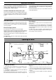
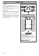
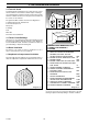
3.4 Terminal Guard
A terminal guard is required if persons could come into contact
with the terminal or the terminal could be subject to damage.
If a terminal guard is required, it must be positioned to provide
minimum of 50mm clearance from any part of the terminal and
be central over the terminal.
The guard should be similar to that shown in diagram 3.5.
A suitable guard can be obtained from.
Tower Flue Components
Morley Rd.
Tonbridge
Kent
TN9 1RA.
Their Reference CGD K3 BL.
3.5 Timber Frame Buildings
If the boiler is to be installed in a timber frame building it should
be fitted in accordance with the Institute of Gas Engineers
document IGE/UP/7/1998. If in doubt seek advice from the local
gas undertaking or Hepworth Heating Ltd.
3.6 Room Ventilation
The boiler is room sealed, so when it is installed in a room or
space, a permanent air vent is not required.
3.7 Cupboard or Compartment Ventilation
Due to the high efficiency and hence low casing temperature of
this boiler, cupboard or compartment ventilation is not necessary.
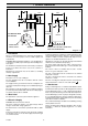
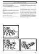
3 Flue Location and Ventilation
A
A
F
G
E
A
G
G
G
B,C
B,C
F
F
K
K
K
C
G
L
L
UNDER CAR PORT etc.
H,I
J
D
F
K
2816
Diagram 3.4
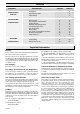
MINIMUM SITING DIMENSIONS FOR
FANNED FLUE TERMINALS
POSITION
MM
A DIRECTLY BELOW AN OPENABLE
WINDOW, AIR VENT, OR ANY
OTHER VENTILATION OPENING 300
B BELOW GUTTER, DRAIN/SOIL PIPE 75
C BELOW EAVES 200
D BELOW A BALCONY OR CAR PORT 200
E FROM VERTICAL DRAIN PIPES AND
SOIL PIPES 75
F FROM INTERNAL CORNERS 300*
G ABOVE ADJACENT GROUND OR
BALCONY LEVEL 300
H FROM SURFACE FACING THE
TERMINAL 600*
I FACING TERMINALS 1200
J FROM OPENING (DOOR/WINDOW)
IN CAR PORT INTO DWELLING 1200
K VERTICAL FROM A TERMINAL 1500
L HORIZONTALLY FROM A TERMINAL 300
M FROM EXTERNAL CORNERS 300
M
Diagram 3.5
TERMINAL GUARD
* It may be necessary to increase this dimension to prevent
staining of adjacent walls depending on weather conditions.