Installation and Servicing Condensing Boilers/ Flexicom cx 24cx G.C.No. 47-047-33 30cx G.C.No. 47-047-34 35cx G.C.No.
Guarantee Registration Thank you for installing a new Glow-worm appliance in your home. Glow-worm appliances are manufactured to the very highest standard so we are pleased to offer our customers a Comprehensive Guarantee. This product is guaranteed for 24 months from the date of installation or 30 months from the date of manufacture, whichever is the shorter, for parts and labour.
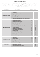
TABLE OF CONTENTS These instructions consist of, Installation, Servicing, Fault Finding, Replacement of Parts and Spares. The instructions are an integral part of the appliance and must, to comply with the current issue of the Gas Safety (Installation and Use) Regulations, be handed to the user on completion of the installation.
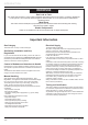
INTRODUCTION WARNINGS Gas Leak or Fault Turn off the gas emergency control valve immediately. Eliminate all sources of ignition, i.e.smoking, blowlamps, hot air guns etc. Do not operate electrical lights or switches either on or off. Open all doors and windows, ventilate the area. Metal Parts This boiler contains metal parts (components) and care should be taken when handling and cleaning, with particular regard to edges.
INTRODUCTION CE Mark Gas Supply This boiler meets the requirements of Statutory Instrument, No. 3083 The Boiler (Efficiency) Regulations, and therefore is deemed to meet the requirements of Directive 92/42/EEC on the efficiency requirements for new hot water boilers fired with liquid or gaseous fuels. Type test for purposes of Regulation 5 certified by: Notified body 0087. Product/production certified by: Notified body 0086. The CE mark on this appliance shows compliance with: 1.
INTRODUCTION Boiler Design Boiler Design Condensate Drain These boilers are designed for use as part of a sealed water central heating system with fully pumped circulation. The pump, expansion vessel and associated safety devices are all fitted within the boiler. The hot water PRE HEAT temperature facility will improve the boilers hot water delivery response. The daily pump and 3 way valve exercise programme combined with the built-in frost protection will help to maintain and protect the boiler.
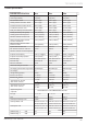
TECHNICAL DATA 1 Boiler Specification 24cx 30cx 35cx Lift weight 36kg (79Ib) 36kg (79Ib) 36kg (79lb) Total weight (installed) 41kg (90Ib) 41kg (90Ib) 41kg (90lb) Gas connection Ø O.D. 15mm. copper 15mm. copper 15mm. copper Heating and return connection Ø O.D. 22mm. copper 22mm. copper 22mm. copper Domestic hot water connection Ø O.D. 15mm. copper 15mm. copper 15mm. copper Condensate connection Ø I.D. 21.5mm. plastic 21.5mm. plastic 21.5mm.
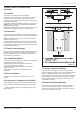
INSTALLATION 13893 2 Boiler Dimensions and Hydraulic Schematic All dimensions are given in millimetres (except as noted). The general arrangment of the boiler is shown in diagram 2.1 and the hydraulic and gas schematic, diagram 2.2. The data label is positioned on the front of the inner casing panel. 13089 Diagram 2.1 -8- Diagram 2.
INSTALLATION 13127 3 Boiler Location, Clearances and Ventilation 3.1 Location This boiler is not suitable for outdoor installation. This boiler may be installed in any room, although particular attention is drawn to the installation of a boiler in a room containing a bath or shower where reference must be made to the relevant requirements. This boiler is suitable for installation in bathroom zones 2 and 3. In GB this is the current I.E.E. WIRING REGULATIONS and BUILDING REGULATIONS.
INSTALLATION 4 Evacuation of Combustion Gas 4.1 Regulation Only flue accessories supplied by Glow-worm must be used. Different flue outlet configurations can be carried out. • Consult your supplier for more information about the other possibilities and associated accessories. 44 mm/m H* and J* See diagram 4.2. These dimensions comply with the building regulations, but they may need to be increased to avoid wall staining and nuisance from pluming depending on site conditions.
INSTALLATION C J V M J E G F H B S K A J N Q U G J J L A 300mm adjacent to a boundary. B The dimension below eaves, balconies and car ports can be reduced to 25mm, as long as the flue terminal is extended to clear any overhang. External flue joints must be sealed with a suitable silicon sealant. C 1500mm between a vertical flue terminal and a window or dormer window. D 1200mm between terminals facing each other. E Vertical flue clearance, 300mm adjacent to a boundary line.
INSTALLATION 4.2 Flue configuration description 4.2.1 4.2.2 Telescopic direct rear flue Ø 60/100 mm Ø 60/100 mm Horizontal concentric flue Ø 60/100 mm or Ø 80/125 mm (C13 type installation) L Ø 60/100 mm L 1 63 4.2.
INSTALLATION 4.2.4 Multiple boiler chimney flue Ø 60/100 mm (C43 type installation) The flue connecting from the appliance to the flue system must be supplied from the manufacturer of the boiler.
INSTALLATION 5.2 Draining Points 5 Water Systems - General 5.1 General This boiler is designed for use as part of a sealed water central heating system with fully pumped circulation. The pump, expansion vessel and associated safety devices are all fitted within the boiler. Draining taps must be provided at all low points of the system, which will allow the entire system to be drained. Draining taps shall be to the current issue of BS2879.
INSTALLATION 5.3 5.3.1 Water treatment General The Glow-worm Flexicom range of boilers have an Aluminium alloy heat exchanger. Water treatment products used in the system should be suitable for use with Aluminium. Existing system- It is ESSENTIAL that prior to installing the new boiler the system is thoroughly flushed. New system- For optimum performance after installation, the boiler and its associated central heating system should also be flushed. 5.3.
INSTALLATION 5 Water systems - Domestic Hot Water 5.4 General All domestic hot water circuits, connections, fittings must be in accordance with the relevant standards and water supply regulations. For GB: Guidance G17 to G24 and recommendation R17 to R24 of the Water Regulations Guide (for Scotland, the Water Byelaws 2000, Scotland). For IE: The current edition of I.S.813 “Domestic Gas Installations”. 5.5 Water Pressure The minimum working pressure to obtain the maximum domestic flow is:24cx 1.0bar 30cx 1.
INSTALLATION The boiler is supplied with a filling device, see diagram 5.1. This filling device is designed to enable the filling and pressurisation of the system in the event of loss of pressure. NOTE: The water pressure at the boiler must be at least 1.2bar to enable filling the boiler to a minimum pressure. If not pressurisation must be carried out by an alternative filling loop. Suitable external filling systems are shown diagramatically, see diagram 5.4.
15708 INSTALLATION H H - Boiler Securing Screw Diagram 6.
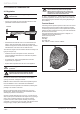
INSTALLATION 13894 6 Installation Preparation 6.1 Appliance Pack Please check the contents of packs as shown in diagram 6.1. The packs are located in the top polystyrene packing. Remove the carton sleeve and top pack then lift the boiler and its polystyrene base support out of the lower pack. 6.2 Site Requirements The boiler mounting wall should be suitable for the weight of the appliance and be true and flat.
INSTALLATION 7 Gas/Water Connections Fit the Central Heating Isolation Valve handles and secure with screws provided. 7.1 System connection Fit the assembled Jig Plate to the Support Plate as shown in diagram 7.2. NOTE: The appliance may contain a small amount of water, place a water container beneath the boiler connections Assemble the Gas service isolation valve and position onto the plastic plug.
INSTALLATION 14811 8 Boiler Fixing 8.1 Boiler Hanging IMPORTANT: With regards to the Manual Handling Operations, 1992 Regulations, the following lift operation exceeds the recommended weight for a one man lift, refer to section 16 Manual Handling. IMPORTANT: Direct Rear Flue only - The direct rear flue must be fitted before hanging the boiler, refer to sections 10.11 to 10.13, and the rear outlet cover plate should be removed.
INSTALLATION 9.1 Safety Discharge Valve 12667 9 Condensate Connections Take the safety discharge pipe, supplied in the pipe pack and the union nut and seal, supplied in the loose items pack and fit as shown in diagram 9.1. This must be extended, using not less than 15mm o.d. pipe, to discharge, in a visible position, outside the building, facing downwards, preferably over a drain. To ease future servicing it is advisable to use a compression type fitting to extend the safety discharge valve tube.
15826 INSTALLATION Diagram 9.
INSTALLATION WARNING: This appliance must be earthed. 13921 10 Electrical Connection ● This appliance must be wired in accordance with these instructions. Any fault arising from incorrect wiring cannot be put right under the terms of the Glow-worm guarantee. ● All system components must be of an approved type. Electrical components have been tested to meet the equivalent requirements of the BEAB. ● Do not interrupt the mains supply with a time switch or programmer.
INSTALLATION 13922 13369 Diagram 10.4 Diagram 10.3 10.4 Electrical Cartridge Securing 10.5 Electrical Connections - Testing With the gas service isolation valve closed and with no demand from any external controls, fit the electrical cartridge into the interface housing, see diagram 10.4. Secure with the two cartridge retaining screws provided in the cartridge body. Carry out preliminary electrical system checks as below: 1. Test insulation resistance to earth of mains cables. 2.
INSTALLATION 7. Close the Domestic Cold Water isolation valve marked ‘B’ using a screwdriver or a 3mm allen key (shown closed in diagram). 8. Close the Central Heating Flow and Return isolation valves marked ‘A’ using a screwdriver or a 4mm allen key (shown closed in diagram). If the manometer kit was used, close drain point marked ‘C’ and remove the manometer. 9.
INSTALLATION 14507 MODE MODE Diagram 11.2 DO NOT operate the boiler without water. Check that all external controls are calling for heat. Set the Central Heating temperature and the Domestic Hot Water temperature to ON by pressing the MODE button on the User Interface until it shows the appropriate symbol or and then pressing the - (minus) SELECTOR button. °C The lighting procedure of the boiler is fully automated. °C display, refer to diagram 12.
INSTALLATION 13072 11.8 Central Heating Range Rating The boilers are fully modulating for central heating, therefore it is not necessary to range rate them, however, if desired, you can adjust the CH output in 1kW increments between: 24cx : 10 - 18kW 30cx : 10 - 24kW 35cx : 10 - 30kW as follows: a) Press and hold the ‘MODE’ and “+” button for 5 seconds. The display will change to flashing ‘0’. b) Use the ‘+’ or ‘-’ button to scroll to 96. c) Press ‘MODE’ and hold 5 seconds to confirm.
MAINTENANCE 1. 2. 3. 4. 5. 6. IMPORTANT NOTES: To ensure the continued efficient and safe operation of the boiler it is recommended that it is checked and serviced at regular intervals. The frequency of servicing will depend upon the particular installation and usage, but in general once a year should be enough. It is the Law that any servicing is carried out by a competent person approved at the time by the Health and Safety Executive.
MAINTENANCE ● Rotate the “throttle”(anti-clockwise to increase), to the required CO2, refer to diagram 12.4 and the “SETTING” column in the table. ● Exit the forced rate function, press the “mode” and “+” buttons simultaneously, this will reset the boiler to the default display. Now proceed to check the minimum rate adjustment. All routine servicing requirements can be achieved by the removal of the front panel, see diagram 12.2. Position the control box into the service position, see diagram 12.3.
MAINTENANCE NOTE: If the functional checks did not indicate poor combustion then it is not necessary to service this component. Ease the securing clips away from the sump to release the retaining catch then push the flue hood up to disengage from the sump, see diagram 12.5. To remove, swivel flue hood 90o and pull down and out, see diagram 12.5. Check seal for wear or damage and replace if necessary. IMPORTANT: Do not allow fixings, nuts, screws, etc.
MAINTENANCE ELECTRICAL CONNECTIONS 14409 14079 SECURING SCREW (3) SECURING NUT SUPPORT BRACKET IGNITION LEAD IGNITER UNIT GAS VALVE ELECTRICAL CONNECTION (removed) EARTH CONNECTION Diagram 12.9 14081 TUBING NUT SPADE CONNECTOR GAS PIPE Diagram 12.7 13128 Diagram 12.10 14288 Diagram 12.8 Diagram 12.
MAINTENANCE 12.5 Condense Trap and Siphonic Drain 14410 FAN CLAMPING BRACKET The condense trap and siphonic drain does not normally need servicing unless material deposits exceed beyond the service fill level, see diagram 12.13. To clean the condense trap remove the sump and rinse with water. SECURING NUTS (6) 12.6 Casing panel seal check NOTE: If the functional checks did not indicate poor combustion then it is not necessary to service this component.
MAINTENANCE 13093 13 Fault Finding 13.1 Preliminary fault finding The following checks should be performed before proceeding onto specific diagnostics: • Check the external electrical supply to the boiler is on and a supply of 230V is present at the ‘L’ and ‘N’ terminals at the installer interface. For access remove and open the electrical cartridge, see diagrams 10.4. and 10.1. Test at the ‘L’ and ‘N’ terminals on the installer interface, refer to diagrams 10.1 and 13.4.
MAINTENANCE 14516 MODE Diagram 13.
MAINTENANCE 13015 DHW 13012 CENTRAL HEATING Diagram 13.
MAINTENANCE 14027 FAULT CODES Diagram 13.
MAINTENANCE State list - To access the state lists the ‘-’ button must be pressed for longer than 5 seconds until it begins to flash ‘S’ and then a number to indicate the state. The state numbers are given below. STATE LISTS no heating required fan pre-run pump pre-run ignition burner on pump / fan overrun fan overrun pump overrun Anti cycling period S.10 S.11 S.13 S.14 S.15 S.16 S.
MAINTENANCE To enter the diagnostics menu follow the procedure below:Press and hold the ‘MODE’ and ‘+’ buttons for approx 5 seconds until the screen changes. Use the ‘+’ or ‘-’ button to select the number 96, this is the password. Hold the ‘MODE’ for approx 5 seconds when 96 is selected, when the screen changes release the button. The screen will flash between ‘L1’ and a number. ‘L1’ indicates you have level 1 access, the number indicates the diagnostic number below.
MAINTENANCE 14 Replacement of Parts 13931 14.1 General Replacement parts that have associated components that need replacing on removal, i.e. ‘O’ ring, seals, gasket, etc., will be supplied and should be fitted. Replacement of parts must be carried out by a competent person approved at the time by the Health and Safety Executive.
MAINTENANCE 14.4 Gas Valve 14.10 Spark Electrode Remove the three securing screws, holding the gas valve to the fan, see diagram 12.7. Remove the gas valve. After re-fitting check the combustion CO2 and adjust if necessary, refer to section 12, Combustion Check. After assembly test for gas tightness and purge in accordance with the current issue of BS6891or in IE, the current edition of I.S.813 “Domestic Gas Installations”. For access, refer to section 14.1. Remove the spark plug lead and earth lead.
MAINTENANCE 14.12 Silencer Assembly (front) 14.18 Domestic Hot Water Thermistor For access, refer to section 14.1. Pull forwards to remove. The silencer is a push fit so no tools or fixings are required for its removal or fitting, see diagram 12.8. For access, refer to section 14.1. Refer to diagram 14.5. Remove the electrical connections from the thermistor. Remove the retaining clip from the DHW pipe. Remove the thermistor from the retaining clip.
MAINTENANCE For access, refer to section 14.1. Refer to section 14.1 and drain the boiler heating circuit. Refer to diagram 14.7. Remove the four cap head screws. Carefully remove the pump head together with cable. Do not strain cable. Support the pump head, unscrew cable cover at the side of pump head and remove. Disconnect wiring from pump head. Reconnect wiring to new pump head and fit cover. Fit the new pump head with ‘O’ ring. Refill, vent and pressurise the boiler and check for leaks. 15587 14.
MAINTENANCE For access, refer to section 14.1. Refer to section 14.1 and drain the boiler hot water circuit. Refer to diagram 14.10. Undo the brass securing nut on the domestic cold water return pipe. Remove the securing clip between the hydroblock and the flow sensor. Remove the electrical connection to the flow sensor. Remove the securing clip holding the brass elbow to the flow sensor. Partially withdraw the flow sensor to allow removal of the electrical connection before full removal of the sensor.
MAINTENANCE 0020107232_03 - 12/14 - Glow-worm FLOW PIPE RETAINING CLIP Diagram 14.12 FLANGED ELBOW 15558 For access, refer to section 14.1. Refer to section 14.1 and drain the boiler heating circuit and the boiler hot water circuit. Remove the silencer front Pull forwards to remove. The silencer is a push fit so no tools or fixings are required for its removal or fitting, see diagram 12.8.
MAINTENANCE 14399 14414 RETAINING CLIP Diagram 14.14 Diagram 14.15 Remove the burner Remove the flanged nuts and studs that secure the burner, note that two studs at the rear also hold the fan clamping bracket, see diagram 14.15. Taking great care not to damage the surface of the burner. NOTE: Replace the burner gasket and follow the tightening sequence when re-fitting the burner, see diagram 14.15. NOTE: Fit all replacement gaskets and seals when re-fitting parts.
MAINTENANCE 14.26 Access to User interface and Main PCB 14.29 Installer Interface Electrical Cartridge For access, refer to section 14.1. Hinge down the control box and unclip the rear cover to gain access. Remove electrical connections from main PCB noting their positions for replacement. Unclip main PCB and remove, see diagram 14.16. Unclip user interface and remove. For replacement, see diagram 14.17 and ensure that the user interface connection cable is refitted.
MAINTENANCE 15 Spare Parts When ordering spare parts, contact Glow-worm’s own service organisation using the telephone number on the inside front cover of this booklet. Please quote the name of the appliance and serial number, to be found on the data label. If ordering from British Gas also quote the G.C. number of the part. Key No. Part No.
MAINTENANCE 16 Manual Handling IMPORTANT. With regards to the Manual Handling Operations, 1992 Regulations, the following lift operation exceeds the recommended weight for a one man lift. General recommendations when handling Clear the route before attempting the lift. Ensure safe lifting techniques are used – keep back straight – bend using legs. Keep load as close to body as possible. Do not twist – reposition feet instead. If 2 persons performing lift, ensure co-ordinated movements during lift.
PRIOR TO CO AND COMBUSTION RATIO CHECK The boiler manufacturer’s installation instructions should have been followed, gas type verified and gas supply pressure/rate checked as required prior to commissioning. As part of the installation process, especially where a flue has been fitted by persons other than the boiler installer, visually check the integrity of the whole flue system to confirm that all components are correctly assembled, fixed and supported. Check that manufacturer’s max.
0020107232_03 - 12/14 Subject to engineering changes 0020107232 GLOW-WORM Nottingham Road, Belper, Derbyshire. DE56 1JT www.glow-worm.co.uk Because of our constant endeavour for improvement, details may vary slightly from those shown in these instructions.