Flexicom Installation and Servicing 12hx G.C. No. 41-315-28 12786 15hx G.C. No. 41-315-29 18hx G.C. No. 41-315-42 24hx G.C. No. 41-315-61 30hx G.C. No. 41-315-67 35hx G.C. No. 41-315-68 High Efficiency Condensing Boilers www.glow-worm.co.uk www.glow-worm.co.
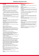
Guarantee Registration Thank you for installing a new Glow-worm appliance in your home. Glow-worm appliances are manufactured to the very highest standard so we are pleased to offer our customers a Comprehensive Guarantee. This product is guaranteed for 24 months from the date of installation or 30 months from the date of manufacture, whichever is the shorter, for parts and labour.
These instructions consist of, Installation, Servicing, Fault Finding, Replacement of Parts and Spares. The instructions are an integral part of the appliance and must, to comply with the current issue of the Gas Safety (Installation and Use) Regulations, be handed to the user on completion of the installation.
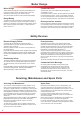
WARNINGS Gas Leak or Fault Turn off the gas emergency control valve immediately. Eliminate all sources of ignition, i.e.smoking, blowlamps, hot air guns etc. Do not operate electrical lights or switches either on or off. Open all doors and windows,ventilate the area. Sheet Metal Parts This boiler contains metal parts (components) and care should be taken when handling and cleaning, with particular regard to edges.
Statutory Requirements CE Mark Gas Supply This boiler meets the requirements of Statutory Instrument, No. 3083 The Boiler (Efficiency) Regulations, and therefore is deemed to meet the requirements of Directive 92/42/EEC on the efficiency requirements for new hot water boilers fired with liquid or gaseous fuels. Type test for purposes of Regulation 5 certified by: Notified body 0087. Product/production certified by: Notified body 0086. The CE mark on this appliance shows compliance with: 1.
Boiler Design Boiler Design Condensate Drain These boilers are designed to provide central heating from a fully pumped open vented or sealed water system and domestic hot water using a fully indirect cylinder. Once the controls are set the boiler operates automatically. A plastic drain pipe must be fitted to allow discharge of condensate to a drain. Condensate should, if possible, be discharged into the internal household draining system.
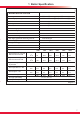
1 Boiler Specification 14730 BOILER SPECIFICATION Lift weight 12hx to 30hx 25kg (55Ib) 35hx 26.5kg (58.4Ib) Total weight (installed) 12hx to 30hx 28kg (62Ib) 35hx 29.5kg (65Ib) Gas connection Ø O.D. 15mm. copper Heating Flow and Return connection Ø O.D. 22mm. copper Condensate connection Ø I.D. 21.5mm. plastic Electrical supply 230V~50Hz Electrical rating 60W fused 3A IP clasification IPX4D Internal fuse rating on main PCB 2A Gas supply (governed meter only) and cat.
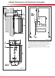
2 Boiler Dimensions and Hydraulic Schematic 13938 13937 Diagram 2.2 2.1 Boiler Dimensions and Hydraulic Schematic All dimensions are given in millimetres (except as noted). The general arrangment of the boiler is shown in diagram 2.1. and the hydraulic and gas schematic, diagram 2.2. The data label is positioned on the front of the inner casing panel. Diagram 2.
3.1 Location This boiler is not suitable for outdoor installation. This boiler may be installed in any room, although particular attention is drawn to the installation of a boiler in a room containing a bath or shower where reference must be made to the relevant requirements. This boiler is suitable for installation in bathroom zones 2 and 3. In GB this is the current I.E.E. WIRING REGULATIONS and BUILDING REGULATIONS. In IE reference should be made to the current edition of I.S.
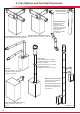
4 Flue Options and Terminal Clearances Ridge Tile Terminal Part No. A2043800 - Section 10, page 31 Plume Management Kit basic set, white, concentric flue (Ø60/100) - Part No. A2044100 for use with Part No. A2043400 and Part No. A2043600 - Section 10, page 36 Top horizontal telescopic flue (Ø60/100) Top horizontal standard flue (Ø60/100) Part No. A2043600 - Section 10, page 20 Part No. A2043400 - Section 10, page 24 Vertical Flue Vertical Flue Adapter, concentric flue (Ø60/100) Part. No.
4 Flue Options and Terminal Clearances 4.1 Flue Options There are various flue options to choose from as illustrated in diagram 4.1. The flue lengths and installation are described in section 10. 4.2 Flue Terminal Position In GB the minimum acceptable siting dimensions for the terminal from obstructions, other terminals and ventilation openings are shown in diagram 4.2. In IE the minimum distances for flue terminal positioning must be those detailed in I.S.813 “Domestic Gas Installations”.
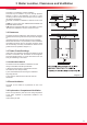
5 Water Systems - General 5.1 General 5.7 Water Treatment This boiler is designed to provide central heating from a fully pumped open vented or sealed water system and domestic hot water using a fully indirect cylinder. Existing system- It is ESSENTIAL that prior to installing the new boiler the system is thoroughly flushed. 5.2 Draining Points Draining taps must be provided at all low points of the system, which will allow the entire system to be drained.
5 Water Systems - Open Vented 13147 5.8 Vented (Open) Water System The boiler must be supplied from an unrestricted water supply taken from a feed and expansion cistern situated at a maximum height of 27 metres (90ft) above the boiler. The cold feed must be 15mm minimum size. The vent must rise continuously and be unrestricted. It is important that the relative positions of the pump, cold feed and open vent are as shown in diagram 5.2. 5.
5 Water Systems - Sealed 5.12 Sealed Water Systems The installation must comply with the appropriate requirements of the current issue of BS4814, BS5449, BS6759, BS6798 and BS7074 Part 1 and 2. See diagram 5.4 for a suggested layout. 5.13 Safety Valve A safety valve must be fitted to a sealed system. It shall be preset, non-adjustable with a lift pressure of 3 bar, incorporating seating of a resilient material, a test device and a connection for drain.
5 Water Systems - Sealed SUPPLY PIPE Provision should be made for replacing water loss from the system using a make up bottle mounted in a position higher than the top point of the system, connected through a non-return valve to the return side of either the heating circuit or the hot water cylinder. Alternatively, provision for make up can be made using a filling loop. BOILER CONTROL VALVE DOUBLE CHECK VALVE 5.
6.1 Appliance Pack Please check the contents of packs as shown in diagram 6.1. The packs are located in the top polystyrene packing. 14805 6 Installation Preparation BOILER SECURING SCREW Remove the carton sleeve and top pack then lift the boiler and its polystyrene base support out of the lower pack. 6.2 Site Requirements The boiler mounting wall should be suitable for the weight of the appliance and be true and flat.
7 Boiler Fixing 14806 7.1 Wall Hanging Bracket The Wall Hanging Bracket is supplied in the main boiler packaging. Reposition the wall template over the flue hole and mark the position of the fixing holes for the hanging bracket, see diagram 7.1. NOTE: Due to the varied site conditions we do not supply fixings and advise that the installer should supply those which are suitable. Drill fixing holes and insert suitable wall plugs.
8 Gas / Water and Appliance Connection 8.2 Water Connections Before connection check the supply of local gas. The gas supply connection is below the boiler, see diagram 8.1. The whole of the gas installation, including the meter, should be inspected, tested for tghtness and purged in accordance with the current issue of BS6891 and in IE the current edition of I.S.813 “Domestic Gas Installations”. Provision is made for the water connections to be made from above the boiler, see diagram 8.1.
9 Condensate Connections 13000 Diagram 9.
10 Telescopic Flue - Length, Preparation and Installation 10.1 Flue Length Multiple Boiler Chimney Flue Length The maximum permissable horizontal flue length is 8 metres plus the flue terminal assembly, this can be achieved by use of the accessories, see diagram 10.3. The flue length must be calculated and installed according to the relevant standards EN 13384-1 and 2 (C43 flue systems only) with reference to the table below and the manufacturers instructions supplied.
10 Telescopic Flue - Length, Preparation and Installation 14826 Diagram 10.2 15418 Diagram 10.
10 Telescopic Flue - Length, Preparation and Installation Refer to diagram 10.2 for kit contents. 12806 10.2 Horizontal Telescopic Flue - A2043600 10.3 REAR Flue If a wall thickness is between 231mm min. to 441mm max. then the flue can be used without extensions. Remove the top flue outlet cover secured with four screws, see diagram 10.4.
10 Telescopic Flue - Length, Preparation and Installation 12929 Diagram 10.8 10.5 Flue Fitting IMPORTANT:The flue seals are sensitive to mineral oil based lubricants. Do not grease the seals. If the seals do need to be lubricated use only water. During the installation of the flue system, ensure that debris such as mortar, filings or swarf are cleared from the flue system before completion. Inspect the flue pipes before fitting and do not install damaged or dented flue components.
10 Standard Flue - Length, Preparation and Installation 10.6 Flue Length Multiple Boiler Chimney Flue Length The maximum permissable horizontal flue length is 8 metres plus the flue terminal assembly, this can be achieved by use of the accessories, see diagram 10.13. However should additional 87.5º or 2 x 45º elbows be used then the length MUST be reduced by 1metre. The diagram 10.11 shows the length achievable by using the kit A2043400.
10 Standard Flue - Length, Preparation and Installation 13222 Diagram 10.12 15418 Diagram 10.
10 Standard Flue - Length, Preparation and Installation 13223 10.7 Standard Horizontal Flue - A2043400 Refer to diagram 10.12 for kit contents. 10.8 REAR Flue Remove the top flue outlet cover secured with four screws, see diagram 10.4. Using these screws inserted into the same holes on the boiler, temporarily secure the flue elbow, measure the distance from the outside wall to the butt joint, see diagram 10.14.
10 Standard Flue - Length, Preparation and Installation IMPORTANT:The flue seals are sensitive to mineral oil based lubricants. Do not grease the seals. If the seals do need to be lubricated use only water. During the installation of the flue system, ensure that debris such as mortar, filings or swarf are cleared from the flue system before completion. Long lengths of flues must be secured to the walls or ceilings they run against. Use at least one fixing bracket for every flue extension that is used.
10 Direct Rear Flue - Length, Preparation and Installation 14809 10.11 Direct Rear flue - Telescopic Part No. A2043500. Refer to diagram 10.19 for kit contents. 10.12 Flue Length Measure the distance from the outside wall to the inside wall face. This measurement must not exceed 512mm (465mm if the upward piping kit is used). If the dimension is less than 291mm DO NOT cut the flue, it can project to a maximum of 600mm, see diagram 10.15. 10.
10 Vertical Flue - Length, Preparation and Installation 10.14 Vertical flue Alternatively use 45º bends to avoid horizontal runs, see (b) in diagram 10.22. The vertical flue system is available as an option where the boiler position does not permit the use of the top horizontal flue system. The terminal siting should be as shown in diagram 4.2. The system is made up from accessories. The accessories include terminal assembly, bends 45º and 87.
10 Vertical - Flue Length, Preparation and Installation 14849 Flue Installation IMPORTANT:The flue seals are sensitive to mineral oil based lubricants. Do not grease the seals. If the seals do need to be lubricated use only water. During the installation of the flue system, ensure that debris such as mortar, filings or swarf are cleared from the flue system before completion. Long lengths of flues must be secured to the walls or ceilings they run against.
10 Vertical - Flue Length, Preparation and Installation A ridge tile terminal is available - part no. A2043800, see diagram 10.24. The installation of a ridge tile will be required. A suitable ridge tile is manufactured by: Aspect East Anglia Limited The Old Mill East Harling NORWICH NR16 2QW Website: www.aspectroofing.co.uk Contact: Chris Haythorpe General Manager - Tile Division Tel: 01953 717777 Fax: 01953 717164 14853 Ridge Tile Terminal Diagram 10.
Completion of Installation With the flue terminal positioned in the roof the length of the final pipe can be determined. If a telescopic length cannot be used, then a standard flue length can be cut to make the correct length. Cut the flue to the desired length measuring from the ‘O’ ring end and discard the plain end of the tube. The cuts must be square and made free of burrs to allow correct assembly. NOTE: The flue pipe is 10mm longer than the air pipe, see diagram 10.28.
15406 10 Twin Flue - Length, Preparation and Installation Secure long flue lengths (horizontal & vertical) to walls or ceiling at every joint or on straight flue runs at every joint and every metre flue run. Diagram 10.
10 Twin Flue - Length, Preparation and Installation 10.15 Twin flue length Multiple Boiler Chimney Flue Length The twin flue system is available as an option when the top horizontal or vertical flue system is not appropriate. The system can provide an independent horizontal air inlet and flue outlet, horizontal air inlet and vertical flue outlet or vertical air inlet and flue outlet via a concentric terminal. The system is made up from accessories, see diagram 10.30.
10 Twin Flue - Length, Preparation and Installation 12985 Installation Details The parts available for a twin flue system installation are shown in diagram 10.30. Boiler Connection IMPORTANT: The flue seals are sensitive to mineral oil based lubricants. Do not grease the seals. If the seals do need to be lubricated use only water. Remove the top flue outlet cover secured with four screws, see diagram 10.4.
12997 10 Plume Management Kit 10.16 Plume Management Kit The Plume Management Kit: Part No. A2044100 (white) or A2044000 (black) can be used to overcome many site issues. The Plume Management Kit will fit to the Top Horizontal Telescopic, Rear Horizontal Telescopic and Standard Horizontal Flue. This enables the flue products to exhaust further away from the boiler, thereby reducing the impact of pluming.
11 Electrical Connection ELECTRICAL CARTRIDGE ● This appliance must be wired in accordance with these instructions. Any fault arising from incorrect wiring cannot be put right under the terms of the Glow-worm guarantee. ● All system components must be of an approved type. Electrical components have been tested to meet the equivalent requirements of the BEAB. ● Do not interrupt the mains supply with a time switch or programmer.
11 Electrical Connection Close the cartridge and secure with the previously removed screw. Push the electrical cartridge into the interface housing on completion of the wiring, see diagram 11.3. Secure with the two cartridge retaining screws provided in the cartridge body. 13906 11.3 Electrical Cartridge Securing FIXING SCREWS 11.4 Electrical Connections - Testing Carry out preliminary electrical system checks as below: 1. Test insulation resistance to earth of mains cables. 2.
12 Commissioning 14513 MODE MODE Diagram 12.2 Commissioning should only be carried out by a competent person approved at the time by the Health and Safety Executive. 12.4 Initial Lighting NOTE: The combustion for this appliance has been checked, adjusted and preset at the factory for operation on natural gas (G20) as defined on the appliance data label. Do not adjust the Gas/Air ratio valve.
12 Commissioning Additionally the safe nominal maximum heat input of the appliance can be achieved at an inlet pressure down to 15mbar. NOTE: The BURNER PRESSURE cannot be measured. Gas Rate Make sure that ALL other gas burning appliances and pilot lights are off. Check the gas rate using the gas meter test dial and stop watch, at least 10 minutes after the burner has lit. The approximate maximum gas rates are: 14249 APPROXIMATE GAS RATES MODEL NATURAL GAS G20 m3/h ft3/h 12hx 1.28 45 15hx 1.60 56.
13 Servicing 1. 2. 3. 4. 5. 6. IMPORTANT NOTES: To ensure the continued efficient and safe operation of the boiler it is recommended that it is checked and serviced at regular intervals. The frequency of servicing will depend upon the particular installation and usage, but in general once a year should be enough. It is the Law that any servicing is carried out by a competent person approved at the time by the Health and Safety Executive.
13 Servicing Before commencing with a service or replacement of parts. The boiler should be isolated from the electrical and gas supplies. 14291 ● Rotate the “throttle”(anti-clockwise to increase), to the required CO2, refer to diagram 13.4 and the “SETTING” column in the table. ● Exit the forced rate function, press the “mode” and “+” buttons simultaneously, this will reset the boiler to the default display. Now proceed to check the minimum rate adjustment. 2.
13 Servicing NOTE: If the functional checks did not indicate poor combustion then it is not necessary to service this component. 14406 13.4 Spark Electrode Ease the securing clips away from the sump to release the retaining catch then push the flue hood up to disengage from the sump, see diagram 13.5. To remove, swivel flue hood 90o and pull down and out, see diagram 13.5. Check seal for wear or damage and replace if necessary. IMPORTANT: Do not allow fixings, nuts, screws, etc.
13 Servicing 14409 14079 SECURING SCREW (3) ELECTRICAL CONNECTIONS SECURING NUT SUPPORT BRACKET IGNITION LEAD IGNITER UNIT GAS VALVE SPADE CONNECTOR EARTH CONNECTION Diagram 13.9 ELECTRICAL CONNECTION (removed) 14081 TUBING NUT GAS PIPE Diagram 13.7 FAN 13128 FAN RETAINING BRACKET SECURING NUT Diagram 13.10 14288 Diagram 13.8 Diagram 13.
13 Servicing 13.8 Casing panel seal check 13.6. Heat Exchanger NOTE: If the functional checks did not indicate poor combustion then it is not necessary to service this component. NOTE: If the functional checks did not indicate poor combustion then it is not necessary to service this component. Remove loose debris from inside the heat exchanger using a soft brush and vacuum cleaner. Check the condition of the seal and replace if worn or damaged.
14 Fault Finding Diagram 14.1 13845 The following checks should be performed before proceeding onto specific diagnostics: • Check the external electrical supply to the boiler is on and a supply of 230V is present at the ‘L’ and ‘N’ terminals at the installer interface. For access remove and open the electrical cartridge, see diagrams 11.4. and 11.1. Test at the ‘L’ and ‘N’ terminals on the installer interface, refer to diagrams 11.1 and 14.4.
14 Fault Finding 13917 KEY br b g/y gy g bk y r w or p pk BROWN BLUE GREEN/YELLOW GREY GREEN BLACK YELLOW RED WHITE ORANGE PURPLE PINK GAS CONTROL VALVE HEATING FLOW THERMISTOR FAN w r wy gy r bk b HEATING RETURN THERMISTOR IGNITER UNIT bk bk b IGNITION ELECTRODE g/y g/y br g/y bk b b br g/y g/y b br w b r w gy r r MAIN CONTROL BOARD r APPLIANCE INTERFACE BOARD FLEXICOM HX Diagram 14.
14 Fault Finding 13012 Diagram 14.
14 Fault Finding In all circumstances press the reset button to clear the fault. If the fault persists, consult the table below. FAULT CODES 14029 Diagram 14.
14 Fault Finding State list - To access the state lists the ‘-’ button must be pressed for longer than 5 seconds until it begins to flash ‘S’ and then a number to indicate the state. The state numbers are given below. 13131 STATE LISTS Diagram 14.
14 Fault Finding To enter the diagnostics menu follow the procedure below:Press and hold the ‘MODE’ and ‘+’ buttons for approx 5 seconds until the screen changes. Use the ‘+’ or ‘-’ button to select the number 96, this is the password. Hold the ‘MODE’ for approx 5 seconds when 96 is selected, when the screen changes release the button. The screen will flash between ‘L1’ and a number. ‘L1’ indicates you have level 1 access, the number indicates the diagnostic number below.
15 Replacement of Parts 15.1 General Replacement of parts must be carried out by a competent person approved at the time by the Health and Safety Executive. 15.7 Fan/Gas valve assembly For access, refer to section 15.1. Undo the tubing nut to remove the gas valve from the gas pipe and any electrical connections, see diagram 13.7. Replacement parts that have associated components that need replacing on removal, ie. ‘O’ ring seals, gasket, etc; will be supplied and should be fitted.
15 Replacement of Parts 12964 15.10 Burner For access, refer to section 15.1. Remove igniter unit, flue hood, fan and gas valve assembly and spark electrode lead, refer to relevant sections. Remove the flanged nuts and studs that secure the burner, note that two studs at the rear also hold the fan clamping bracket, see diagram 13.10. NOTE: The burner gasket should be inspected but will not need replacing unless there are signs of wear or damage. IMPORTANT: Do not allow fixings, nuts, screws, etc.
15 Replacement of Parts For access, refer to section 15.1. Refer to diagram 15.3. Remove the electrical connections from the thermistor. Remove the retaining clip from the return pipe. Remove the thermistor from the retaining clip. Note that the polarity of the wiring to thermistor is unimportant. 14379 15.13 Heating Return Thermistor RETURN PIPE 15.14 Heat Exchanger For access, refer to section 15.1. Drain down the boiler heating circuit Remove the silencer front Pull forwards to remove.
15 Replacement of Parts Remove the heat exchanger Remove the burner Undo the screws securing the flanged elbow on the top right hand side of the heat exchanger and remove the retaining clip from the flanged elbow, see diagram 15 5. Remove the six flanged nuts and two studs that secure the burner, note that the two studs also hold the fan clamping bracket, see diagram 15.7. Remove retaining clip from the flanged elbow on the bottom of the heat exchanger, see diagram 15.4.
15 Replacement of Parts 15.15 Casing Seal 15.18 Fuse - Main PCB - Control Box Refer to Section 13.8. For access, refer to section 15.16. The fuse is located at the top left hand corner of the main PCB, see diagram 15.8. 15.16 Access to User interface and Main PCB 15.19 Installer Interface Electrical Cartridge For access, refer to section 15.1. Hinge down the control box and unclip the rear cover to gain access. Remove electrical connections from main PCB noting their positions for replacement.
16 Spare Parts Key No. Part No.
17 Manual Handling IMPORTANT. With regards to the Manual Handling Operations, 1992 Regulations, the following lift operation exceeds the recommended weight for a one man lift. General recommendations when handling Clear the route before attempting the lift. Ensure safe lifting techniques are used – keep back straight – bend using legs. Keep load as close to body as possible. Do not twist – reposition feet instead. If 2 persons performing lift, ensure co-ordinated movements during lift.
18 Declaration of Conformity 14506 59
Glow-worm, Nottingham Road, Belper, Derbyshire. DE56 1JT Because of our constant endeavour for improvement, details may vary slightly from those shown in these instructions. Glow-worm, Nottingham Road, Belper, Derbyshire. DE56 1JT www.high-efficiency.info 0020057279-04 01.