221691B.12.00 Instructions for Use Installation and Servicing 0863 To b e l e f t w i t h t h e u s e r Hideaway 40B G.C. No. 41 313 16 Balanced Flue Boiler BS 6332 BS 5258 This is a Cat I2H Appliance Reference in these instructions to British Standards and Statutory Regulations/Requirements apply only to the United Kingdom. For Ireland the rules in force must be used.
Important Information Testing and Certification This boiler is tested and certificated for safety and performance. It is therefore important that no alteration is made to the boiler, without permission, in writing, from Hepworth Heating Ltd. Any alteration not approved by Hepworth Heating Ltd., could invalidate the certification, boiler warranty and may also infringe the current issue of the Statutory Requirements, see Section 1.3. CE Mark This boiler meets the requirements of Statutory Instrument No.
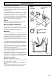
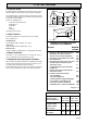
Notes and General Information PIEZO IGNITION BUTTON 'C' Please read these instructions and follow them carefully for the safe and economical use of your boiler. The boiler is automatic in operation, once the pilot has been lit and the controls set. GAS CONTROL KNOB 'A' 5993 Instructions for Use Glow-worm Hideaways are central heating boilers, to provide heating and if required, an indirect domestic hot water supply.
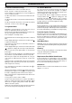
Instructions for Use To Connect an Electrical Plug To Turn the Boiler Off The standard colours of three core flexible cable are, For short periods, turn the boiler thermostat control knob “B” anticlockwise to “O”. The pilot will stay alight. To relight the main burner turn thermostat control knob “B” clockwise to the desired setting between “MIN” and “MAX”. Brown - live, Blue - neutral, Green and Yellow - earth.
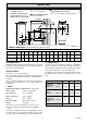
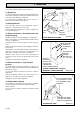
General Data GAS CONNECTION Rc 1/2 (1/2 in. B.S.P.T.) ✝ A SPECIAL TOP CASING TO SUIT 600mm (235/8 in.) WORKTOPS IS AVAILABLE WATER CONNECTIONS Rc1 (1in. B.S.P.T.) WATER CONNECTIONS Rc1 reduced with DISTRIBUTOR TUBE to Rc 3/4 (3/4 in. B.S.P.T.) (pumped return) ✝ F(MIN.) A CL P CL H ✽ N L G(MIN.) CD K B 0684 ✽ Refer to BOILER CASING HEIGHT diagram CL M J E Diagram 1.1 GENERAL DIMENSIONS - given in millimetres (Approx.
General Data 0982 1.3 Statutory Requirements The installation of this must be carried out by a competent person and must be in accordance with the relevant requirements of the current issue of: Manufacturer’s instructions supplied. BOILER WITHOUT TOP CASING BOILER WITH TOP CASING To floor level MAX.900 (351/2 in.) MID. 890 (35in.) MIN. 860 (34in.
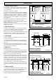
1 General Data The base temperature is within the requirements of the current issue of BS5258. The boiler may stand on a wooden floor but a metal base plate is required to protect plastic tiles and similar floor coverings. 1.8 Heating System Controls When the boiler is to be installed level with work surfaces and the like, minimum clearances should be provided as shown in diagram 1.3. Work tops which overhang the cupboard sides, almost in contact with the casing top, require a larger minimum air gap.
2.3 Gravity Domestic and Pumped Heating 0870 2 Water Systems 22mm VENT It is recommended that a cylinder thermostat is used to prevent the stored water temperature becoming unnecessarily high when the central heating pump is off. 15mm COLD FEED The domestic primary flow and return must be 28mm o.d. The installation must comply with the current issue of BS5546 and BS6700, see diagram 2.1. 1 metre MIN. 27metres MAX.
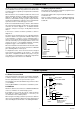
3 Flue and Ventilation 1112 3.4 Terminal Guard A terminal guard is required if persons could come into contact with the terminal or the terminal could be subject to damage. C A If a terminal guard is required, it must be positioned to provide a minimum of 50mm clearance from any part of the terminal and be central over the terminal. B,C B,C G A Guards are available from: F Tower Flue Components Ltd., Morley Road, Tunbridge, Kent. TN9 1RA G L K F F A E K L K G G G Under Car Port etc.
4 Installation Before fixing the boiler make sure that the location selected is in accordance with the requirements of Section 1.7. 0888 UPPER CASING BRACKET 4.1 Unpacking The boiler casing panels are packed separately within the main carton and are designed to enable gas and water connections to be made before fitting the casing panels. CAPTIVE No.8 SCREW (8) NUT The casing brackets, distributor tube and loose items, in a plastic bag, are packed in the top fitment. 4.
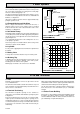
4 Installation 4.6 Pipework 0874 ALTERNATIVE FLOW POSITIONS When the front tappings are used, it is essential that any pipework of fittings do not project more than shown in diagram 4.5. When using a rear tapping with Rc (1in BSP) fitting for 28mm od pipework, it is recommended that a short nipple and an R thread (BSP) to copper elbow is used.
4 Installation 4.8 Boiler Connection Connect the boiler to the system pipework. Make the gas connection to the service cock, at the lower right hand side of the boiler. BALANCED FLUE DUCT FROM BOILER 360 (141/4 in.) PREPARED HOLE IN THE WALL 3 (1/8 in.) MIN. 0876 240 (91/2 in.) 485 (19 in.) ;;; ;;; ;;; ;;; ;;; ;;; ; PREPARED HOLE IN THE WALL DIMENSIONS WALL PLATE 0891 BOILER AIR DUCT Diagram 4.
5 Casing Location / Fitting Fit four plastic pegs into the appropriate holes in the top casing, if being fitted, see diagram 5.3. The plastic pegs are a tight fit and are best pushed home with a flat faced tool. The top casing can be arranged to fit flush with or overhang the door. The top casing is reversible to match, when level with, square or rolled edge work surfaces. PLASTIC PEG (4) Push the top casing on to all four side casing locations.
6.1 Control Box Cable Connection Warning. This boiler must be earthed. COVER Remove the screw and cover from the mains inlet connector, supplied loose, see diagram 6.1. Using heat resistant flexible cable of suitable length and rating as in Section 1.6, connect the three cables to the required terminals in the connector. Secure the outer sheathing with the cable clamp. L N E 0878 6 Electrical Wiring SLOTS Engage slots and lugs, replace cover and secure with screw.
7 Commissioning When the pilot is alight, keep control button “A” fully pushed in for about 15 seconds. If the pilot burner fails to stay alight, repeat the lighting procedure but now keep the control button pushed in for a little longer. Please ensure the “Benchmark” logbook is completed and left with the user. 7.1 Commissioning and Testing the Boiler , a safety lock prevents If the gas control knob “A” is turned to it being turned on again.
Check the operation of the flame failure device as follows: with the main burner alight, turn gas control knob “A” fully anti, the main and pilot burners will go out. clockwise to its stop Relighting the boiler will not now be possible as a safety device has been activated. After 60 seconds the flame failure device should have closed, indicated by a click from the gas valve. Do not attempt to relight until 3 minutes have elapsed. 13 (1/2 in.) SPARK GAP APPROX. DIMENSION FLAME DIMENSION 3-4mm. (1/8 in.
8 Servicing Before starting a service, turn off the gas supply at the service cock, see diagram 8.1 and isolate the boiler from the electrical supply. 1870 Servicing must be carried out by a competent person. THERMOSTAT CAPILLARY LOCATION WASHER Always test for gas soundness after completing a service or replacement of parts. 8.1 Boiler Flueways Pull door forwards at the top to disengage studs and lift to release from slots, see diagram 7.3.
8 Servicing 6139 8.2 Burner and Injector Follow instructions to remove the cover, burner and controls assembly as in Section 8.1. Remove the two screws and nuts securing the burner support bracket to the combustion chamber cover, see diagram 8.7. Remove the graphite coated nuts on the supply feed pipe at the rear of the burner to release the burner, take care not to damage the pilot burner and shield when removing. FLUEWAY BAFFLE Clean burner thoroughly.
9 Replacement of Parts 9.3 Thermocouple Before removing or replacing any parts, turn off the gas supply at the gas service cock, see diagram 8.1 and isolate the electrical supply to the appliance. Remove the door and plinth as in Section 8.1 Always test for gas soundness after replacing any gas carrying component. Disconnect thermocouple by unscrewing nuts at gas valve and pilot burner, see diagrams 9.1 and 9.3. Release the cable clips and the thermocouple can be withdrawn. 9.
9 Replacement of Parts 6124 240V~ 50Hz MAINS SUPPLY FUSED AT 3A THERMOSTAT N L GAS VALVE C N/C ORANGE RED GRN/YEL BLUE CHASSIS EARTH Diagram 9.2 9.6 Piezo Unit and Ignition Lead 0935 CONTROL BOX WIRING SECURING SCREW (2) AND NUT (2) Follow the relevant instructions in Section 8.1. Pull off ignition lead at piezo unit, see diagram 9.1. THERMOCOUPLE SPARK ELECTRODE To replace lead also, pull off the lead at the spark electrode terminal, see diagram 9.3.
10.1 Electrical L GAS VALVE CONTROL SOLENOID 4 3 THERMOSTAT IMPORTANT: The preliminary electrical system checks as contained in the British Gas Multimeter Instruction Book, or similar publication, are the first checks to be carried out during a fault finding procedure. On completion of the service fault finding task which has required the breaking and remaking of electrical connections, then the checks, earth continuity, polarity and resistance to earth must be repeated.
0194 10 Fault Finding - Thermocouple Disconnect appliance thermocouple from the multi-functional control. Check that all connections are clean and in good condition. Fit test meter interrupter into the magnet unit. Fit appliance thermocouple into the test meter interrupter. Hold down control tap in ignition position. Ignite burner, allowing thermocouple to attain operating temperature. Measure the OPEN CIRCUIT voltage. Is voltage greater than 15mV? NO Faulty thermocouple. Replace.
10 Fault Finding - Pilot 0905 PILOT WILL NOT LIGHT START HERE Does pilot stay alight when gas valve knob is released? Check gas line-open all cocks, rectify any blockages, purge out any air. Does pilot light? NO NO YES Apply match to pilot burner instead of pressing piezo unit button. Does pilot light? NO PILOT SATISFACTORY YES Undo tubing nut at pilot burner. Turn gas valve knob to Pilot/Ign. Press gas valve knob.
11 Spare Parts If ordering from British Gas you will also require the GC appliance number off the data label and the required spare part GC number. When ordering spare parts quote the part number and description, stating the model and serial number off the data label “L”, see diagram 7.1. 1 2 6286 The key number in the first column of the list will help identify each part in diagram 11.1. 4 3 12 6 5 8 11 9 7 10 Diagram 11.1 Key No Part No. Description GC Part No.