
Manual

6
221691B
1.3 Statutory Requirements
The installation of this must be carried out by a competent
person and must be in accordance with the relevant requirements
of the current issue of:
Manufacturer’s instructions supplied.
The Gas Safety (Installation and Use) Regulations, Building
Regulations, Local Water Company Bye-laws, The Building
Standards (Scotland) Regulations, (applicable in Scotland),
Health and Safety at Work Act, Control of Substances Hazardous
to Health, Electricity at Work Regulations and any applicable
local regulations.
Detailed recommendations are contained in the current issue of
the following British Standards and Codes of Practice,
BS6891, BS5440 Part 1 and 2, BS6798, BS5449, BS5546,
BS6700, BS7478, BS7593, BS7671.
Manufacturer’s instructions must not be taken as overriding
statutory requirements.
1.4 B.S.I Certification
This boiler is certificated by B.S.I., for safety and performance.
It is, therefore, important that no alteration is made to the boiler
unless agreed, in writing, by Hepworth Heating Ltd.
Any alteration not approved by Hepworth Heating Ltd., could
invalidate the B.S.I. certification, boiler warranty and could
infringe the current issue of the Statutory Requirements.
1.5 Gas Supply
The gas installation should be fitted in accordance with the
current issue of BS6891.
The supply from the governed meter must be of adequate size
to provide a steady inlet working pressure of 20mbar (8in wg) at
the boiler.
On completion test the gas installation using the pressure drop
method and suitable leak detection fluid, purge in accordance
with the current issue of BS6891.
1.6 Electrical
WARNING. This boiler must be earthed.
The electrical installation must be carried out by a competent
person. All external components shall be of the approved type
and shall be connected in accordance with the current issue of
BS7671 and any local regulations which apply.
Connection of the boiler and any system controls to the mains
supply through an unswitched shuttered socket outlet and 3A
fused 3 pin plug, both to the current issue of BS1363.
Alternatively, a 3A fused double pole isolating switch may be
used, having a minimum double pole contact separation of
3mm, serving only the boiler and system controls.
Heat resistant cable of at least 75mm
2
(24/0.20mm), to the
current issue of BS6500 Table 16, must be used for all
connections within the boiler casing, to the control box, pump
etc.
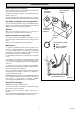
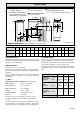
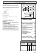
1.7 Boiler Location
The casing can be fitted to the boiler at various heights. The top
casing can be discarded if preferred, when fitting the boiler
under a low worktop or fixture. Refer to diagram 1.2.
The boiler must stand on a level floor, conforming with local
authority requirements and building regulations.
BOILER CASING HEIGHT(S)
Diagram 1.2
MAX.900 (35
1
/
2
in.)
MID. 890 (35in.)
MIN. 860 (34in.)
MAX.867 (34
1
/
8
in.)
MID. 857 (33
3
/
4
in.)
MIN. 827 (32
1
/
2
in.)
BOILER
WITH TOP
CASING
BOILER
WITHOUT
TOP CASING
BOILER CASING ALTERNATIVE
HEIGHT POSITIONS
MIN.
MAX.
MIN.
MAX.
MID.
MID.
To
floor
level
FLOOR
LEVEL
0982
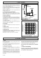
General Data
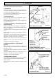
Diagram 1.3
Diagram 1.4
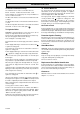
MINIMUM CLEARANCES
LEVEL WITH WORKTOP
MINIMUM CLEARANCES
UNDER WORKTOP, FIXTURES
0866
320 MIN.
(12
5
/
8
in.)
320 MIN.
(12
5
/
8
in.)
CUPBOARDS
WORKTOP
0865
10
(
3
/
8
in.)
10
(
3
/
8
in.)
10
(
3
/
8
in.)
10
(
3
/
8
in.)
3 (
1
/
8
in.)
BOILER
WITH
TOP
CASING
BOILER
WITHOUT
TOP
CASING
CUPBOARD
CUPBOARD
CUPBOARD
10 (
3
/
8
in.)
WORKTOP OR FIXTURE
BOILER
BOILER
5
(
3
/
16
in.)
10
(
3
/
8
in.)