
Manual

7
221691B
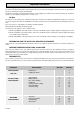
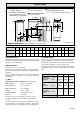
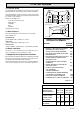
FRONT CLEARANCE
Diagram 1.5
0906
700 (27
1
/
2
in.)
BOILER
WALL OR
FIXTURE
1 General Data
The base temperature is within the requirements of the current
issue of BS5258. The boiler may stand on a wooden floor but
a metal base plate is required to protect plastic tiles and similar
floor coverings.
When the boiler is to be installed level with work surfaces and
the like, minimum clearances should be provided as shown in
diagram 1.3. Work tops which overhang the cupboard sides,
almost in contact with the casing top, require a larger minimum
air gap. Flush sided fixtures require the same overall minimum
space but can have a reduced air gap on one side.
Boilers to be installed under work tops or fixtures, with or without
the casing top fitted should be positioned to provide minimum
clearances as shown in diagram 1.4. To facilitate minimum
clearances it may be necessary to modify kitchen units and
fixtures.
A front access clearance should be provided as shown in
diagram 1.5.
The boiler may be installed in any room, although particular
attention is drawn to the requirements of BS7671 with respect
to the installation of a boiler in a room containing a bath or
shower. Any electrical switch should be so positioned that it
cannot be touched by a person using the bath or shower. The
electrical provisions of the Building Standards (Scotland)
Regulations apply to such installations in Scotland.
Where the installation of the boiler will be in an unusual location,
special procedures are necessary the current issue of BS6798
gives detailed guidance on this aspect.
A compartment used to enclose the boiler must be designed
and constructed specifically for this purpose. An existing
cupboard or compartment modified for the purpose may be
used. Details of essential features of cupboard or compartment
design are given in the current issue of BS6798.
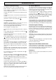
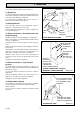
2 Water Systems
2.1 Water Pressure Head
The boiler shall only be connected to a cistern water supply with
a minimum head of 1metre (3ft3in) and a maximum head of
27metres (90ft) which has an open vent in the system.
The working pressure must be within the range 0.1bar to 2.7bar
(1.3 to 39lbftin
2
).
The boiler MUST NOT be connected to a sealed water system.
2.2 Inhibitor
Attention is drawn to the current issue of BS5449 and BS7593
on the use of inhibitors in central heating systems.
If an inhibitor is to be used in the system, contact should be
made with the inhibitor manufacturers so that they can
recommend their most suitable product.
When using in an existing system take special care to drain the
entire system, including the radiators, then thoroughly cleaned
out before fitting the boiler whether or not adding an inhibitor.
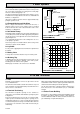
Diagram 2.1
0869
27metre
Max.
PUMP
To Heating
Circuit
INDIRECT
CYLINDER
22mm VENT
15mm COLD FEED
REFER TO BS 5546
28mm
Distributor tube in
pumped return
connection
BOILER
C
L
DRAIN OFF
COCK
1.8 Heating System Controls
The heating system should have installed: a programmer and
room thermostat controlling the boiler.
Thermostatic radiator valves may be installed in addition to the
room thermostat.
Note: For further information, see The Building Regulations
1991 - Conservation of fuel and power, 1995 edition - Appendix
G, table 4b.