221910F.10.04 Instructions for Use Installation and Servicing To b e l e f t w i t h t h e u s e r 7319 Micron 30FF G.C. No. 41-047-46 Fanned Flue Boiler This is a Cat I2H Appliance Reference in these instructions to British Standards and Statutory Regulations/Requirements apply only to the United Kingdom. For Ireland the current edition of I.S.813 "Domestic Gas Installations" must be used. The instructions consist of three parts, User, Installation and Servicing Instructions.
Important Information TESTING AND CERTIFICATION This boiler is tested and certificated to EN483 for safety and performance. It is therefore important that no alteration is made to the boiler, without permission, in writing, from Glow-worm. Any alteration not approved by Glow-worm, could invalidate the certification, boiler warranty and may also infringe the current issue of the Statutory Requirements. CE MARK This boiler meets the requirements of Statutory Instrument No.
Instructions for Use Introduction All CORGI Registered Installers carry a CORGI ID card, and have a registration number. Both should be recorded in your boiler Logbook. You can check your installer is CORGI registered by calling CORGI direct on :- 01256 372300. Please read these instructions and follow them carefully for the safe and economical use of your boiler. The Micron series are fanned flue boilers designed to provide central heating and indirect domestic hot water.
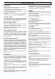
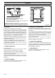
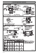
Installation - 1 General D B PUMPED FLOW J H TOP / SIDE FLUE OPTION E M PUMPED RETURN 6784 A R L K C C WATER CONNECTIONS F REAR FLUE OPTION G P GAS CONNECTION MODEL 30FF A B Q C N D E F G H 262 75 102 360 139 500 68 85 J 115 STD/EXD. EASYFIT K 115 126 L 156 M N P 100 104 23 40 Q R 35 108 STD/EXD. EASYFIT All dimensions are given in millimetres Diagram 1.1 IMPORTANT NOTICE The Current I.E.E. Wiring Regulations.
1 General 1.3 Gas Supply and preferably adjacent to the appliance. It should supply the appliance only and be easily identifiable as so doing. The gas installation shall be in accordance with the relevant standards. Alternatively, an unswitched shuttered socket outlet and 3A fused 3 pin plug, both to the current issue of BS1363 may be used provided that they are not used in a room containing a bath or shower. In GB this is BS6891. In IE this is the current edition of I.S.
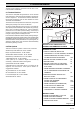
7064 1 General with Easyfit top flue fitted, * 190mm with standard/extended top flue fitted, * 160mm 20mm without top flue fitted Increased top clearance is required if flow pipe enters from below to permit access to air vent. MINIMUM CLEARANCES FROM WALLS, CEILING, FLOOR, CUPBOARD, WORKTOPS AND INFLAMMABLE MATERIALS Diagram 1.3 1.12 Boilers in a Compartment 1.
2 Flue and Ventilation The flue must be installed in accordance with the rules in force in the countries of destination. N 2.1 Terminal Position The minimum acceptable siting dimensions for the terminal from obstructions, other terminals and ventilation openings are shown in diagram 2.1. For Ireland the minimum distances for flue terminal positioning must be those detailed in I.S.813 "Domestic Gas Installations".
2 Flue and Ventilation 7056 2.3 Terminal Guard A terminal guard is required if persons could come into contact with the terminal or the terminal could be subject to damage. If a terminal guard is required, it must be positioned to provide a minimum of 50mm clearance from any part of the terminal and be central over the terminal, see diagram 2.2. A suitable guard, reference Type “K3”, can be obtained from: Tower Flue Components Ltd., Morley Road, Tonbridge, Kent. TN9 1RA Diagram 2.
3 Water Systems 3.8 Inhibitor 3.15 Filling a Sealed Water System Attention is drawn to the current issue of BS5449 and BS7593 on the use of inhibitors in central heating systems. Provision for filling the system at low level must be made. The installation should comply with the appropriate requirements of the current issue of BS 5449.
9354 4 Flue and Appliance Preparation Diagram 4.
4 Flue and Appliance Preparation 7148 NOTE: Make sure that the ductings do not slope down towards the boiler. 4.1 Flue Position and Length OPTIONAL FLUE COLLAR Determine flue application, length and terminal position before starting. Refer to diagram 4.1. If you are using a Flue Bend or a Vertical Flue Kit, please follow the instructions supplied with the kit. To make a neat finish to the flue outlet a flue collar kit, part No. 900850, with instructions, is available, see diagram 4.2.
4 Flue and Appliance Preparation Seal the joint with the tape provided. 7102 WITH WALL LINER KIT ONLY If the flue system requires the addition of flue extension kits, drill, seal and secure them with the self tapping screw and tape provided. The completed flue system must not exceed 3 metres, see relevant part of diagram 4.1.
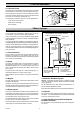
5 Boiler Installation 5.1 Unpacking 6769 VIEW ON COVER TOP Open the carton, check the items supplied against the boiler pack contents list on the carton flap. CASE SECURING SCREWS 5.2 Boiler Preparation With the boiler still in the bottom tray, remove the casing front cover. To do this open the controls cover first, then by undoing the two screws at the bottom and the one at the top, lift the front cover off, see diagram 5.1. Place front cover in a safe place on one side until required.
NOTE: Remove the electrical connections by pulling insulation boots only. MOUNTING BRACKET Remove the securing screw at the front, see diagram 5.5. 12005 5 Boiler Installation The fan assembly may now be slid forward. Rear Flue fixing. Fit the fan elbow and secure with jubilee clip to the fan outlet, do not tighten yet, see diagram 5.7. Fit the retaining clamp of the fan elbow, bending the straps around the fan elbow raised clamping surfaces but do not fasten the clasp, see diagram 5.8.
5 Boiler Installation 7150 5.5 Gas Connection REAR FLUE FIXING Make the gas connection to the Rc1/2in gas service cock, see diagram 6.2. The whole of the gas installation, including the meter, should be inspected, tested for soundness and purged in accordance with the current issue of BS6891 and in IE the current edition of I.S.813 "Domestic Gas Installations". SCREWS (4) 5.6 Control Box Access Slacken the control box securing screw, see diagram 5.10. Swing the box out on its hinge. 5.
5 Boiler Installation 5.8 Pump Connection 1. Test insulation resistance to earth. The pump must be connected to the external controls. 2. Test earth continuity and short circuit of all cables. 3. Test the polarity of the mains. 5.9 Testing The installer is requested to advise and give guidance to the user of the controls scheme used with the boiler. Checks to ensure electrical safety must be carried out by a competent person. Fit the casing.
6 Commissioning IMPORTANT NOTE: The warning notice attached to the front of the boiler casing must only be removed by the user. 7318 FASCIA Please ensure the “Benchmark” logbook is completed and left with the user. 6.1 All Systems Commissioning should be carried out by a competent person in accordance with the current issue of BS6798. Do not operate the boiler wthout water. UNDER ALL CIRCUMSTANCES the case must be correctly fitted and sealed, unless fault finding.
6 Commissioning 6.4 Testing - Electrical Table 2 Turn the boiler temperature control knob fully clockwise to the maximum setting, which is approx. 82OC (180OF). 30FF The lighting sequence is automatic as follows: APPROX. GAS RATE The fan will operate for 10 seconds prior to the start of the ignition sparks, the gas valve solenoids will open and the burner will light. This is shown by the "Burner Lit" LED on the control panel lighting up. MAX. m3/h ft3/h 1.00 35.
7 Instructions to the User Instruct and demonstrate the safe and efficient operation of the boiler, heating system and domestic hot water system. Advise the user, that to ensure the continued efficient and safe operation of the boiler it is recommended that it is checked and serviced at regular intervals. The frequency of servicing will depend upon the particular installation and usage, but in general once a year should be enough.
REMEMBER: When replacing a part on this appliance, use only spare parts that you can be assured conform to the safety and performance specification that we require. Do not use reconditioned or copy parts that have not been clearly authorised by Glow-worm. SAMPLING POINT 7231 8 Servicing Products of Combustion Check NOTE: To obtain a products of combustion reading, remove the cap from the sampling point, located on top of the inner casing, see diagram 8.1. Connect the analyser tube onto the nipple.
8 Servicing 6801 8.4 Injector With the burner removed the injector can be inspected and cleaned as necessary, see diagram 8.5. For cleaning do not use a wire or sharp instrument on the hole. If removed, use a little suitable sealant on the external thread when refitting to make sure a gas tight seal is made. 8.5 Operational Checks After completing a service and before fitting the case, check condition of the case seal and renew if necessary.
10270 9 Fault Finding Before carrying out fault finding, ensure that gas, electricity and water are available to the boiler. Ensure that any external controls are calling for heat and circuit water is cold. If Reset LED is lit - check water system for overheating, reset by turning temperature control knob off and on. If the LED coding is showing an ignition failure, reset the boiler by turning the control knob off and on. Do not operate the boiler without combustion chamber front fitted.
10271 10275 9 Fault Finding Diagram 9.
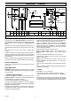
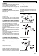
AIR PRESSURE SWITCH KEY br b g/y g bk p y r 12382 9 Fault Finding BROWN BLUE GREEN/YELLOW GREY BLACK PURPLE YELLOW RED g y r b p FAN GAS CONTROL VALVE SAFETY TEMPERATURE LIMITER br br ELECTRODE THERMISTOR bk bk br bk br br b g/y g/y A B P.C.B (CONTROL BOARD) JUMPER POSITION g y p r b T3.15A FUSE RESET LED BURNER LIT LED bl b b MAINS SUPPLY 230V~50Hz g/y br BLOCK CONNECTOR KEY TO TERMINAL BLOCK LS N bk LS = LIVE (Switched) N = NEUTRAL = EARTH MAIN b g/y g/y Diagram 9.
10 Replacement of Parts 10272 IMPORTANT NOTES NOTE: Replacement of parts must only be carried out by a competent person. Before replacing any parts isolate the boiler from the electrical supply and turn the gas supply off at the gas service cock, see diagram 6.2. Unless stated otherwise, all parts are replaced in the reverse order to removal. After replacing any parts always test for gas soundness and if necessary carryout functional check of controls. 10.1 Access Gain Access as Section 5.2. 10.
10 Replacement of Parts from boiler by removing the hinge pins, see diagram 5.10. Rear Carefully pull the control knob and extension piece away from the PCB. With the side insulation removed the rear insulation can be removed and replaced. Carefully pull the board away from its supports. Disconnect the electrical plugs by slightly bending back the retaining latches to allow withdrawal. ELECTRICAL PLUG When refitting refer to wiring diagram 9.4.
10 Replacement of Parts 10.11 Air Pressure Switch, Part No. 227032 - diagram 10.6 7227 SECURING SCREW (2) Gain Access as Section 5.2. Remove the air pressure tube and electrical connections from the switch, release the screws and remove the switch. When fitting the replacement make sure that the plastic tube is fitted as shown in diagram 10.6 and the electrical connections are as shown in diagram 9.4. AIR PRESSURE SWITCH 10.12 Fan, Part No. 227033 - diagram 10.7 Refer to Section 5.3.
11 Spare Parts 11.1 Part Identification The part number and the diagram location will help to identify the part. 11.2 Ordering When ordering any spare parts please quote the number and description from the list together with the model name and serial number. Ref Part No Description Location GC Part No 1 2000801159 Multifunctional control Diagram 10.4. E24851 2 227033 Fan Diagram 10.7. E24884 3 227032 Air pressure switch Diagram 10.6.