
Owner manual


5
221910F
and preferably adjacent to the appliance. It should supply the
appliance only and be easily identifiable as so doing.
Alternatively, an unswitched shuttered socket outlet and 3A
fused 3 pin plug, both to the current issue of BS1363 may be
used provided that they are not used in a room containing a bath
or shower.
Wiring to the boiler must be PVC 85
0
C insulated cable, not less
than 0.75mm
2
(24/0.20mm).
1.5 Contents of Packaging
The boiler is delivered in one pack with the flue system packed
separately.
1.6 Water System
This boiler may be fitted to an open vented or a sealed water
system.
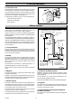
1.7 Draining Tap
System
A draining tap must be provided at the lowest points of the
system which will allow the entire system and hot water cylinder
to be drained.
Draining taps should be to the current issue of BS2879.
Boiler
A draining point is fitted at the bottom right hand side of the heat
exchanger.
When draining is required cover the controls to avoid water
damage.
If required remove the combustion chamber front cover to
improve access.
1.8 Safety Valve
A safety valve need not be fitted to an open vented system.
1 General
1.3 Gas Supply
The gas installation shall be in accordance with the relevant
standards.
In GB this is BS6891.
In IE this is the current edition of I.S.813 "Domestic Gas
Installations".
The supply from the governed meter must be of adequate size
to provide a steady inlet working pressure of 20mbar (8in wg)
at the boiler.
On completion test the gas installation for soundness using the
pressure drop method, purge in accordance with the above
standard.
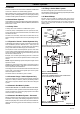
1.4 Electrical Supply
WARNING: This boiler must be earthed.
All system components shall be of an approved type and shall
be connected in accordance with the current issue of BS7671
and any applicable local regulations.
External wiring must be correctly earthed, polarised and in
accordance with the relevant standards.
In GB this is BS 6891.
In IE this is the current edition of I.S.813 "Domestic Gas
Installations".
Connection of the boiler and system controls to the mains
supply must be through a common isolator and must be fused
3A, maximum. This method of connection must be by a fused
double pole isolating switch, with a minimum contact separation
of 3mm on both poles. The switch should be readily accessible
9462
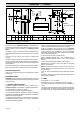
PMS = 3.0 bar, is: Maximum water-side operating pressure.
The appliance flue type is a C
12
,C
22
,C
32
and C
52
. This refers to a
concentric or twin flue where the fan is downstream of the heat
exchanger. The C
12
is a horizontal flue termination, the C
22
is a
shared duct system (seduct), the C
32
is a vertical flue termination and
the C
52
has separate ducts to two terminals that may terminate in
zones of different pressure.
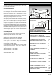
DATA
LABEL
7316
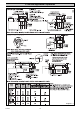
Diagram 1.2
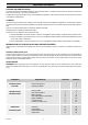
TABLE 1.
TOTAL DRY WEIGHT
(Including Terminal)
LIFT WEIGHT
WATER CONTENT
GAS CONNECTION
ELECTRICITY RATING
WATER CONNECTION
ELECTRICITY SUPPLY
DATA LABEL
36.4 kg (80lb)
29.7 kg (65.34lb)
2.2 litre (0.48 gallon)
66W Internal fuse Type T3.15A
2x22mm copper pipes from
back of case
230V~50Hz,fused 3A
Top left hand inside of case
Rc
1
/
2
in.