
Owner manual


7
221910F
2 Flue and Ventilation
The flue must be installed in accordance with the rules in force
in the countries of destination.
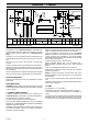
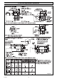
2.1 Terminal Position
The minimum acceptable siting dimensions for the terminal
from obstructions, other terminals and ventilation openings are
shown in diagram 2.1. For Ireland the minimum distances for
flue terminal positioning must be those detailed in I.S.813
"Domestic Gas Installations".
The terminal must be exposed to the external air, the position
allowing free passage of air across it at all times.
Car ports or similar extensions of a roof only, or a roof and one
wall, require special consideration with respect to any openings,
doors, vents or windows under the roof. Care is required to
protect the roof if it is made of plastic sheeting. If the car port
consists of a roof and two or more walls, seek advice from the
local gas company before installing the boiler.
If the terminal is fitted within 600mm below plastic guttering or
painted soffit an aluminium shield 1500mm long should be fitted
immediately beneath the guttering or eaves. If the terminal is
fitted within 450mm below painted eaves or a painted gutter, an
aluminium shield 750mm long should be fitted immediately
beneath the guttering or eaves.
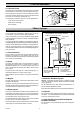
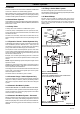
2.2 Flue Options
There are various flue systems to choose from, as follows:
Standard Top Outlet Flue Pack - Pt.No. 230483
Easyfit Top Outlet Flue Pack - Pt. No. 232057
Standard Rear Outlet Flue Pack - Pt. No. 230482
Extended Top Outlet Flue Pack - Pt. No. 230487
1 Metre Extension Kit - Pt. No. 230484
A flue system up to 3 metres in length can be made by
connecting 1 metre flue extension kits together.
Optional Wall Liner Kit No. 900862
A Flue Bend Kit or Vertical Flue Kit up to 4 metres can be
supplied, see Glow-worm's "Flue Options Guide" for
configurations available.
45
o
Flue Bend Pack - Pt. No. 230485
90
o
Flue Bend Pack - Pt. No. 230486
In Line Flue Adapter Kit - Pt. No. 230488
Vertical Flue Kit No. 458115
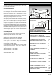
MINIMUM SITING DIMENSIONS FOR
FANNED FLUE TERMINALS POSITION MM
HORIZONTAL FLUES
A DIRECTLY BELOW, ABOVE OR
HORIZONTALLY TO AN OPENING, AIR BRICK,
OPENING WINDOW, AIR VENT, OR ANY
OTHER VENTILATION OPENING 300
B BELOW GUTTER, DRAIN/SOIL PIPE 25
C BELOW EAVES 25
D BELOW A BALCONY OR CAR PORT 25
E FROM VERTICAL DRAIN PIPES AND
SOIL PIPES 25
F FROM INTERNAL/EXTERNAL CORNERS
OR TO A BOUNDARY ALONGSIDE THE
TERMINAL 25
G ABOVE ADJACENT GROUND OR
BALCONY LEVEL 300
H FROM SURFACE OR A BOUNDARY
FACING THE TERMINAL 600
I FACING TERMINALS 1200
J FROM OPENING (DOOR/WINDOW)
IN CAR PORT INTO DWELLING 1200
K VERTICAL FROM A TERMINAL 1500
L HORIZONTALLY FROM A TERMINAL 300
VERTICAL FLUES
M FROM ADJACENT WALL TO FLUE 300
N FROM ANOTHER TERMINAL 600
P FROM ADJACENT OPENING WINDOW 1000
Q ABOVE ROOF LEVEL 300
Diagram 3.3
A
A
E
G
G
B,C
B,C
F
K
C
UNDER CAR PORT etc.
H,I
J
D
F
K
F
L
M
Q
N
P
11508