221786B.11.00 Instructions for Use Installation and Servicing 2143 To b e l e f t w i t h t h e u s e r 60CF G.C. No. 41 319 50 Open Flue Boiler BS 6332 BS 5258 This is a Cat I2H Appliance Reference in these instructions to British Standards and Statutory Regulations/Requirements apply only to the United Kingdom. The instructions consist of three parts, User, Installation and Servicing Instructions, which includes the Guarantee Registration Card.
Important Information Testing and Certification This boiler is tested and certificated for safety and performance. It is therefore important that no alteration is made to the boiler, without permission, in writing, from Hepworth Heating Ltd. Any alteration not approved by Hepworth Heating Ltd., could invalidate the certification, boiler warranty and may also infringe the current issue of the Statutory Requirements, see Section 1.4.
Instructions for Use Introduction Cleaning Please read these instructions and follow them carefully for the safe and economical use of your boiler. WARNING. This appliance contains metal parts (components) and care should be taken when handling and cleaning, with particular regard to edges. The Ultimate series are central heating boilers designed to provide heating and indirect domestic hot water. Clean the casing occasionally by wiping it over with a damp soapy cloth or dry polishing duster.
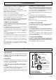
Instructions for Use Connecting an Electrical Plug Turn thermostat knob “B” faulty anticlockwise to the “O” Off position. The colours of three core flexible cable are, Brown - live, Blue - neutral, Green and Yellow - earth. Push in control knob “D”, keep pushed in, push and release piezo button “A” until the pilot lights. As the marking on your plug may not correspond with these colours continue as follows: Look through window “E”.
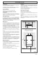
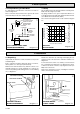
0024M 1 General Data 392 115 345 INSIDE DIAMETER OF SOCKET FOR 100mm (4in) NOMINAL DIAMETER FLUE CL 544 23 149 252 168 CL FLUE 679 803 780 39 88 Diagram 1.1 WATER CONNECTION RC1 (1in. BSPT) GAS CONNECTION RC1/2 (1/2 in. BSPT) GENERAL DIMENSIONS (all dimensions in mm) 1 General Notes and Information 1.3 Range Rating This boiler is for use on natural gas G20. The boiler is range rated and may be adjusted to suit the individual system requirements.
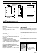
1 General Data 1.6 Electrical Supply 1.12 Boiler Clearances WARNING: This boiler must be earthed. Refer to diagram 1. Instructions for Use. All system components shall be of an approved type and shall be connected in accordance with the current issue of BS7671 and any applicable local regulations. The boiler must be positioned so that at least the minimum operational and servicing clearances are provided.
2 Flue and Ventilation 2.2A Boilers in a Room or Space The flue must be installed in accordance with the recommendations in the current issue of BS5440 Part 1. A purpose designed ventilation opening must be provided on an outside wall of the building, this opening may be either, directly into the room or space containing the boiler, or into an adjacent room or space which has an internal permanent air vent of the same size to the room containing the boiler. The flue should be kept as short as possible.
3 Water Systems 3.4 Pump It is important the flow and return connections are made as shown in diagram 3.2. This should be fitted on the flow pipe and have isolating valves fitted each side, integral, if possible. These connections may be fitted on the opposite side to that shown but always in the same relative positions. The pump should be set to give a temperature difference of 11oC (20oF) between flow and return, with the boiler thermostat set at “MAX” which is about 82oC (180oF). 2124 3.
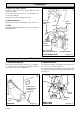
4 Installation 2943 Note: It is NOT recommended that the boiler be placed in an upright position. If it is unavoidable great care must be taken not to damage the gas valve, to avoid this it is suggested that support be placed under the boiler, positioned as shown in diagram 4.3. B G 4.2 Preparation D Use the wall frame and refer to diagram 4.4, mark out the position of the fixing holes, making sure they are square. Remove the wall frame and drill holes to suit plugs and screws provided.
4 Installation 2122 4.4 Water Circulation System Complete the water connections to the boiler pipework, using compression fittings. Fill, vent and cold flush the system as recommended in the current issue of BS6798. Visually check for and put right any water leaks. 4.5 Gas Connection FLUE CLEANING DOOR Make the gas connection to the flanged Rc1/2 gas service cock. 4.6 Flue FLUE SOCKET GUIDE (2) Install the flue pipework and seal to the flue socket in accordance with normal practice.
5 Electrical Connection Connect to the terminal strip, as shown in diagram 5.3. 5.3 Testing Secure the cable into the clamp, as shown in diagram 5.2. Checks to ensure electrical safety should be carried out by a competent person. Make sure that there is sufficient cable to allow the control box to be temporarily hooked into the front slot, to allow for servicing. It is essential that the polarity is correct. Replace the control box by reversing the information given above in Section 5.1.
6 Commissioning To set the burner pressure, operate the boiler for 10 minutes, remove the multifunctional control cover, if not already removed, as above. Adjust the gas burner pressure by screw “F” until the required pressure is obtained, see the relevant Table 1 for setting pressures. Check the operation of the flame failure device, with the burner alight, as follows:- Slide the control button “K” inwards and release, the main burner and pilot will go out.
6 Commissioning Relight the main burner and allow the system to warm up. Check that the boiler thermostat and all external controls are operating as required. There should be no undue noise in the system and no pumping over of water or entry of air at the open vent. Do not attempt to adjust the thermostat calibration screw. 5312 COVER Allow the system to reach maximum temperature and check for water soundness.
8 Servicing and Replacement of Parts It will be necessary to purge the pipework and multifunctional control before relighting, refer to Commissioning. 8.1 Access Refer to diagram 4.1 and 6.1. Slide the controls cover off. Undo the screws and remove the outer case. 8.5 Multifunctional Control/Solenoid Replacement Lift the combustion chamber shield clear of the lugs and remove. Refer to diagram 8.3. Remove the multifunctional control cover as described in Section 8.4. 8.
8 Servicing and Replacement of Parts Ease the supply tube from the pilot injector and unscrew the injector. 8.6 Main Injector Gain access as Section 8.1. Remove main burner as Section 8.2. 8.9 Thermocouple Remove the main burner injector from the right hand side of the combustion chamber. Gain access as Section 8.1. Refer to diagram 6.4. Disconnect thermocouple from the interrupter from the gas valve. Clean or replace as necessary. Do not clean with wire or sharp instrument.
8 Servicing and Replacement of Parts Disconnect the pilot supply tube by unscrewing the tubing nut. Remove the pilot burner by unscrewing the fixing at the left hand side. 8.14 Flue Blockage Safety Device Reassembly Note: When refitting check that the spark gap is correct and ensure that the thermocouple tip will be enveloped as shown in diagram 6.3. Remove the flue cleaning door, refer diagram 4.6. 8.11 Thermostat Remove capillary from clips. Gain access as Section 8.1. Refer to diagram 5.2, 8.5, 8.
9 Fault Finding 5291 PILOT WILL NOT LIGHT START HERE Does pilot stay alight when multi-functional control knob is released? Check flue blockage safety device has not operated, check gas line-open all cocks, rectify any blockages, purge out any air. Does pilot light? NO NO YES YES PILOT SATISFACTORY Apply match to pilot burner instead of pressing piezo unit button. Does pilot light? NO YES Does pilot flame envelop thermocouple? Undo tubing nut at pilot burner. Turn gas valve knob to Pilot/Ign.
9.1 Pilot 5316 9 Fault Finding FLUE BLOCKAGE SAFETY DEVICE Refer to chart 9.1. 9.2 Thermocouple Refer to chart and diagram 9.2. 9.3 Electrical CONNECTION "E" Refer to diagram 9.3 and 9.4. The preliminary electrical system checks as contained in a multimeter instruction book are the first checks to be carried out during fault finding.
0899/A 9 Fault Finding Carry out preliminary electrical checks to make sure the electrical supply is available at the boiler. Check that external controls are calling for heat. Make sure that the system is filled, the flue blockage safety device is reset, the gas supply is available and the pilot is lit. Isolate electrical supply to the control box. Remove the control box cover and check all cables. Turn boiler thermostat to Max. Is there continuity between 'C' and 'NC'. NO YES Faulty thermostat.
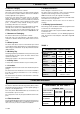
10 Replacement Parts 1 8057 If replacement parts are required, apply to your local supplier. Please quote the name of the appliance and its serial number, found on the data label on the right hand side of the control box, after removal of the cover. 4 5 3 2 7 13 12 9 14 10 8 6 11 Diagram 10.1 Key No Part No Description G.C. Part No.