
User guide


6
221786B
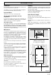
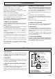
COMPARTMENT
VENTILATION
REQUIREMENTS
ULTIMATE 60CF
COMPARTMENT AIR VENT TABLE 2.
FROM ROOM
OR SPACE
208cm
2
32in
2
416cm
2
64in
2
104cm
2
16in
2
208cm
2
32in
2
HIGH LEVEL LOW LEVEL
VENT AREA VENT AREA
FROM
OUTSIDE
1 General Data
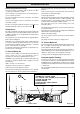
1.6 Electrical Supply
WARNING: This boiler must be earthed.
All system components shall be of an approved type and shall
be connected in accordance with the current issue of BS7671
and any applicable local regulations.
Connection of the boiler and system controls to the mains
supply should be through a common isolator fused at 3A,
maximum. This method of connection should be by a switched
spur box with a minimum contact separation of 3mm in both
poles. It should be clearly marked, showing its purpose,
preferably positioned close to the boiler.
Alternatively an unswitched socket outlet and three pin plug,
fused 3A, to the current issue of BS1363 may be used.
Wiring to the boiler must be PVC insulated cable at least
0.75mm
2
(24/0.20mm) to the current issue of BS6500 Table 16.
1.7 Contents of Packaging
The boiler is delivered in one pack which contains:
Boiler with outer case and wall frame, side panels, burner,
combustion chamber shield, flueway baffle and loose items
pack.
1.8 Water System
The boiler shall only be used on an unrestricted open vented
system with the water supply taken from a feed and expansion
tank, having a head between 1m (3ft 3in) minimum and 27m
(90ft) maximum.
1.9 Draining Tap
A draining tap must be provided at the lowest point of the system
which will allow the entire system, the boiler and hot water
cylinder to be drained.
Draining taps shall be to the current issue of BS2879.
1.10 Safety Valve
A safety valve need not be fitted to an open vented system.
1.11 Location
WARNING. Open flue boilers must not be installed in a private
garage.
The boiler must not be installed in a room used or intended to
be used as sleeping accommodation or a room containing a
bath or shower.
The boiler must be mounted on a flat wall which is sufficiently
robust to take its weight.
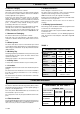
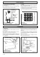
TABLE 1
RANGE RATING
Min.
NOMINAL
kW
HEAT INPUT
(GROSS)
Btu/h
NOMINAL
kW
HEAT
OUTPUT
Btu/h
BURNER
mbar
SETTING
PRESSURE
in.w.g
APPROX.
m
3
/h
GAS
RATE
ft
3
/h
BURNER :- K8277
PILOT :- 7215
INJECTOR
MARKING
17.7 23.13
60,400 78,900
ULTIMATE 60CF RANGE RATING
Max.
7.5 13.0
3.0 5.2
13.19 17.59
45,000 60,000
1.71 2.25
60 79
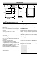
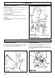
1.12 Boiler Clearances
Refer to diagram 1. Instructions for Use.
The boiler must be positioned so that at least the minimum
operational and servicing clearances are provided.
Additional clearances may be required for installation.
If fixtures are positioned next to the boiler they should be made
removable for access to pipework.
Sufficient clearance must be left in front of the boiler for
servicing.
1.13 Heating System Controls
The heating system should have installed: a programmer and
room thermostat controlling the boiler.
Thermostatic radiator valves may be installed in addition to the
room thermostat.
Note: For further information, see The Building Regulations
1991 - Conservation of fuel and power, 1995 edition - Appendix
G, table 4b.
Important Note
The boiler is fitted with a Flue Blockage Safety Device, which
will shut down the boiler if there is an unacceptable spillage of
products at the draught diverter.
This safety device MUST NOT under any circumstances be
interfered with or put out of action.
The safety device must only be replaced with the Glow-worm
parts.
2.1 Flue Connection
The integral draught diverter makes the combustion performance
independent of conditions in the secondary flue, but an efficient
flue is necessary to ensure a trouble free installation.
2 Flue and Ventilation