
User guide


8
221786B
Diagram 3.2
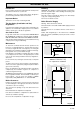
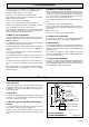
FULLY PUMPED CIRCULATION
SYSTEM (DIAGRAMMATIC)
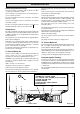
Diagram 3.3
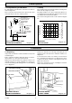
PRESSURE
LOSS OF BOILER
1metre Min.
27 metres
Max.
22mm VENT &
15mm COLD FEED
TO BE FITTED IN
ACCORDANCE
WITH BS 6798
INDIRECT
CYLINDER
ALTERNATIVE
SYSTEM
CONTROL
VALVES
HEATING
SYSTEM
PUMP
MIDWAY BETWEEN
BOILER TAPPINGS
120
100
80
60
40
20
0
14.7
11.7
8.8
5.9
0
0
5
10 15
20 25 30
Flow rate (litres/minute)
Water pressure loss
(mm head of water)
HEAT SETTING (kW) To give a water
flow rate differential of 11˚C (20˚F)
0023M
2124
2126
3.3 Pumped Heating and Hot Water
It is important the flow and return connections are made as
shown in diagram 3.2.
These connections may be fitted on the opposite side to that
shown but always in the same relative positions.
3 Water Systems
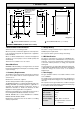
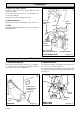
Diagram 4.2
SECURING BOILER
TO WALL FRAME
2129
BOILER
SECURING
SCREW(S)
3.4 Pump
This should be fitted on the flow pipe and have isolating valves
fitted each side, integral, if possible.
The pump should be set to give a temperature difference of
11
o
C (20
o
F) between flow and return, with the boiler thermostat
set at “MAX” which is about 82
o
C (180
o
F).
The resistance through the boiler can be found from diagram
3.3.
4 Installation
4.1 Unpacking
Unpack and check that the contents, listed below, are present
and undamaged:-
Boiler, combustion chamber shield, side panels x 2, burner,
flueway baffle, loose items pack (with check list).
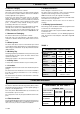
With the boiler still in the bottom tray, slide the controls cover
upwards and remove as shown in diagram 4.1. Remove the
outer case by undoing, and retaining), the two screws and lifting
off, see diagram 4.1.
Release the wall frame by removing and keeping the two
retaining screws at the back of the combustion chamber, see
diagram 4.2.
To remove the boiler, turn it over, sideways, out of the bottom
tray, see diagram 4.3, taking care not to damage the controls,
so that it is face down on the floor, exposing the four Rc1 (1in
BSP) water connections.
Remove the remaining loose items, including the wall frame
which is in the bottom of the tray.
Diagram 4.1
CONTROLS COVER &
OUTER CASE REMOVAL
OUTER CASE
SECURING SCREW
CONTROLS COVER
8044