condens Installation and Servicing Ultracom2 cxi 24cxi G.C. No. 47-019-10 30cxi G.C. No. 47-019-11 35cxi G.C. No.
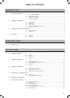
Table of contents IN T R O D U C T I O N 1 Instructions guidance..........................................................................................................................3 1.1 1.2 1.3 1.4 2 Appliance description..........................................................................................................................3 2.1 2.2 2.3 2.4 2.5 3 Safety devices ........................................................................................................3 Data label...
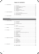
Table of contents 12 Commissioning ................................................................................................................................25 12.1 12.2 12.3 12.4 12.5 12.6 12.7 12.8 12.9 13 Specific adjustment . ........................................................................................................................28 13.1 13.2 13.3 13.4 14 Switching on..........................................................................................................
INTRODUCTION INTRODUCTION 1 Instructions guidance 1.1 Product documentation The instructions are an integral part of the appliance and must be handed to the user on completion of the installation in order to comply with the current regulation. • Carefully read the manual, to understand all the information to enable safe installation, use and servicing. No liability can be accepted in the event of damage for not complying with the guidance in this instruction manual.
INTRODUCTION 2.2 Data label 2.4 The data label certifies the country where the appliance is intended to be installed. 2.4.1 Regulation and statutory requirements CE Mark This boiler meets the requirements of Statutory Instrument, No. 3083 The Boiler (Efficiency) Regulations, and therefore is deemed to meet the requirements of Directive 92/42/EEC on the efficiency requirements for new hot water boilers fired with liquid or gaseous fuels.
INTRODUCTION 2.
INTRODUCTION 3 Safety instructions and regulations 3.1 Safety instructions If the gas pressure at the input of the appliance is outside the range specified, the appliance must not be put into operation. e Incorrect installation can cause electric shock or appliance damage. • Never disable security devices and do not try to adjust them. • Use only new O-rings and gaskets. • After having completed work on gas or water carrying components, check for their tightness.
INTRODUCTION Gas Supply The gas installation must be in accordance with the relevant standards. In GB, this is BS6891. In IE, this is the current edition of I.S.813 “Domestic Gas Installations”. The supply from the governed meter must be of adequate size to provide a steady inlet working pressure of 20mbar (8in wg) at the boiler. On completion, test the gas installation for tightness using the pressure drop method and suitable leak detection fluid, purge in accordance with the above standard.
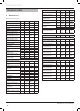
technical data TECHNICAL DATA 5 Boiler, type C13, C33, C43 Unit Gas category 24 cxi 30 cxi 35 cxi ll2H3P ll2H3P ll2H3P SEDBUK 2005 rating % 90.3 90.3 90.4 SEDBUK 2009 rating % 89.0 89.3 89.3 kW 18.5 25 30.6 kW 4.9 5.9 8.5 kW 18.2 24.6 30 Heating Maximum heating input power Minimum heating output power at 80/60°C (P min.) Maximum heating output power at 80/60°C (P max.) Minimum heating output power at 50/30°C (P min.) Maximum heating output power at 50/30°C (P max.
INSTALLATION INSTALLATION i 6 6.1 6.1.1 the flue from inside the property, which may necessitate clearance larger than those specified in diagram below. All the drawings dimensions are shown in mm. ØA Appliance location mi ØA n. Location Instructions Before choosing a site for the appliance, carefully read the safety warnings and installation manual. • Ensure that wall to which the appliance will be mounted on is structurally safe in order to support the weight of the appliance. 0 mi n.
INSTALLATION 7 Appliance installation 7.1 4.5 4.6 4.7 Scope of delivery The appliance is delivered in a single carton with a document pack and fittings. i 7.2 7.2.1 Guarantee envelope pack Magnetic lighting instruction label Gas conversion label Recommendations before installing Domestic hot water circuit design The flues package will be ordered according to the configuration of the installation. Water pressure The minimum working pressure to obtain the maximum domestic flow is 1,0 bar.
INSTALLATION 7.2.2 Heating circuit design Bypass The boiler is fitted with an automatic bypass which can be adjusted to suit your system requirements. 6 5 7 • Ensure that under no circumstances does the flow rate drop below the figure specified, refer to chapter "Technical data". Filling the sealed system i The water pressure at the boiler must be at least 1.2bar to operate the filling loop. If the pressure is less than 1.2bar an external filling loop must be fitted.
INSTALLATION Water treatment 160 Ø150** Ø130** Existing system- It is essential that prior to installing the new boiler the system is thoroughly flushed. 160 Ø125* Ø105* New system- For optimum performance after installation, the boiler and its associated central heating system should also be flushed. 156 63 Flushing shall be carried out in accordance with BS 7593, a chemical cleanser can be used either Sentinel X300, X400 or Fernox F3 are suitable.
INSTALLATION Flue hole cutting • Mark the position of the flue centre. • Remove the wall template, then drill the flue hole. i 2 The flue is designed with an internal fall of 44mm/ metre (2.5o), therefore the hole can be drilled horizontally. • Use a 105mm diameter core drill for external access flue installation (60/100 flue) (80/125 flue ► Ø130mm). 1 • Use a 125mm diameter core drill for internal access only flue installation (60/100 flue) (80/125 flue ► Ø150mm).
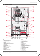
INSTALLATION 8.2 • Only use original seals supplied with the appliance. Safety Discharge Valve • Check that there are no leaks. Repair if necessary. 6 7 8 7 5 6 4 3 2 1 Key 1 Heating return isolating valve + sealing washer ¾" 2 Cold water inlet isolating valve + sealing washer ¾" 3 Gas service isolating valve with pressure test point + sealing washer ½" 4 Domestic hot water outlet isolating valve + sealing washer ¾" 5 Heating flow isolating valve + sealing washer ¾" 6 Connection Ø O.D.
INSTALLATION 8.3 Connection to the condensate trap a Condensate produced by the appliance is mildly acidic (pH 3.5 - 5.0). Use protective gloves b Condensate must only be discharged in accordance with these instructions. i The volume of condensates evacuated can reach about 15 litres per day for a detached house. This volume is negligible compared to the volume of waste water discharged by a house, because the condensates are diluted in this water.
INSTALLATION - 16 - 0020112601_02 - 10/12 - Glow-worm
INSTALLATION 9 Evacuation of combustion gas 9.1 Regulation b Only flue accessories supplied by Glow-worm must be used. Different flue outlet configurations can be carried out. • Consult your supplier for more information about the other possibilities and associated accessories. 44 mm/m 1 Carports or similar extensions of a roof only, or a roof and one wall, require special consideration with respect to any openings, doors, vents or windows under the roof.
INSTALLATION Position Position of the flue terminal Horizontal flues directly below an opening, air brick, A opening windows B above an opening, air brick, opening windows horizontally to an opening, air brick, opening C windows D below gutter, drain/soil pipe E below eaves F below a balcony or car port G from vertical drain pipes and soil pipes H from internal/external corners H* to a boundary alongside the terminal I above adjacent ground or balcony level J* from surface or a boundary facing the terminal
INSTALLATION 9.2 9.2.1 a Flue configuration description Horizontal concentric flue Ø 60/100 mm or Ø 80/125 mm (C13 type installation) If necessary, you must install a terminal protection kit. Type Max length Ø 60/100 Ø 80/125 10 m 25 m Each time an additional 90° bend is necessary (or 2 at 45°), the length (L) must be reduced by 1 m. 9.2.
INSTALLATION 9.2.3 Multiple boiler chimney flue Ø 60/100 mm (C43 type installation) Model 24cxi 30cxi 35cxi At min thermal load (40°C/30°C) 45 37 41 At max thermal load (80°C/60°C) 65.7 63.4 71.4 Exhaust temperature (°C) b The flue connecting from the appliance to the flue system must be supplied from the manufacturer of the boiler.
INSTALLATION 11.3 • Do not use cable greater than 10 mm in diameter for the electrical connections. Connection of the whole electrical system and any heating system controls to the electrical supply must be through a common isolator. All system components must be of an approved type. • Do not interrupt the mains supply with a time switch or programmer. The boiler is suitable for installation in bathroom zones 2 and 3. 11.
INSTALLATION 11.3.1 230V permanent supply 11.3.2 a All cables connected to the appliance should be permanently fixed to the wall. i This appliance will not operate without a link or system controls fitted. 2 230V permanent supply + 230V system controls a All cables connected to the appliance should be permanently fixed to the wall. i This appliance will not operate without a link or system controls fitted.
INSTALLATION 11.4 e External accessories Under no circumstances must any mains voltage be applied to any of the terminals on the 24v connection plug. 2 1 3 X17 24 V BUS RT 24V BUS T° ext X18 4 23 0 V Key 1 24V room thermostat connector 2 Ebus room thermostat connector or Ebus radio receiver 3 Outdoor sensor connector 4 Overheating safety connector for heating floor • Fit external controls in accordance with the rules in force.
INSTALLATION 11.
INSTALLATION 12 Commissioning i At the time of commissioning, complete all relevant sections of the Benchmark Checklist located on the inside back pages of this document. The commissioning should be carried out by a competent person approved at the time by the Health and Safety Executive and in accordance with the current issue of BS6798. 12.
INSTALLATION 12.3 Filling DHW Circuit • Open the various hot water taps to fill the DHW circuit. 12.4 Filling the Condensate Trap • Check that the appliance has been installed in accordance with the instructions. • Check the integrity of the flue system and flue seals. • Check the integrity of the appliance combustion circuit and relevant seals. • Check that all internal/external controls are calling for heat. • Check that the gas service isolation is open.
INSTALLATION 12.6 Gas rates The supply from the governed meter must be of adequate size to provide a steady inlet working pressure of 20mbar (8in wg) at the boiler. • On completion, test the gas installation for tightness using the pressure drop method and suitable leak detection fluid, purge in accordance with the above standard.
INSTALLATION 13 Specific adjustment 13.1 Output/pressure curve Ultracom2 30cxi A Heating circuit adjustment It may be necessary to adjust the by-pass to the design of the system. The boiler is delivered pre-set open 1/2 turn (1).
INSTALLATION • Press on button or under the symbol value of the parameter. to modify the • Do likewise for each parameter that needs to be modified. • Press for more than 3 seconds on the button the configuration menu. Code Parameter to exit Factory setting Unit Description 18 25 30 Modifiable parameter d.00 Maximum heating power kW Choose a value: 24cxi ► 5 to 18 kW 30cxi ► 6 to 25 kW 35cxi ► 8 to 30 kW d.01 Pump over-run time - heating min. Choose a value between 2 and 60. 5 yes min.
INSTALLATION 13.2.2 After Sales Service settings • Press for more than 7 seconds on the button to access the configuration menu. The screen displays "0". • Press on button or under the symbol After Sales Service password. and enter the to validate. The screen displays the • Press on parameter "00" and its value "XX”. • Press on button or parameter to modify. under the symbol or under the symbol • Press on button value of the parameter.
INSTALLATION 13.2.3 Status of the appliance • Press button under the symbol for more than 3 seconds to learn the current state of functioning of the appliance. The screen displays the state of the appliance "S.XX". • Press button menu. Status S.00 S.01 S.02 S.03 S.04 S.05 S.06 S.07 S.08 Status S.10 S.11 S.13 S.14 S.15 S.16 S.17 Status S.20 S.21 S.23 S.24 S.25 S.26 S.27 S.28 Status S.30 S.31 S.32 S.34 S.39 S.40 S.41 S.53 S.54 S.96 S.
INSTALLATION 13.4 Re-check and restart • Once the appliance is installed, check the operation of the appliance. • Start the appliance to ensure that any adjustments operate correctly and check that the appliance operates safely. • Check the gas-tightness and water-tightness of the appliance and eliminate any leaks. • Check that the flue joints are tested for tightness and fitted in accordance with the instructions. • Check the entire control and safety system, its settings and its operation.
MAINTENANCE MAINTENANCE 15.1.1 To ensure the continued efficient and safe operation of the boiler it is recommended that it is checked and serviced at regular intervals. The frequency of servicing will depend upon the particular installation and usage, but in general once a year should be enough. Check the electrical installation 2 3 1 It is the Law that any servicing is carried out by a competent person approved at the time by the Health and Safety Executive.
MAINTENANCE 15.2 Fault memory • This menu allows you to display the 10 most recent failure codes registered by the appliance. • In order to display the fault code memory, simultaneously and under the symbol for more press the buttons than 7 seconds. • The screen will display the first fault "01" (record) and "F.XX" (fault code). • To display the other faults registered by the appliance, press the button or under the symbol . for more than 3 seconds to exit this • Press button menu.
MAINTENANCE Fault Description codes Cause Solution F26 Fault in gas valve motor. Disconnected or defective cables • Check the gas valve connections. • Check the operation of the gas valve. • Check the operation of the condensate pump (option). F27 Flame detection fault. Abnormal flame detection • Check the flame detection electrode. • Check the main board. • Check the igniter unit.
MAINTENANCE 15.4 Functional flow diagram 15.4.1 Central Heating 15.4.
MAINTENANCE 16 Gas conversion adjustments 2 3 In order to operate with a gas other than that provided from the factory, it is necessary to some adjustments to the gas valve. This conversion should only be carried out by a competent person approved at the time by the Health and Safety Executive. • During the conversion to Propane, use of a suitable flue gas analyser is necessary.
MAINTENANCE Gas adjustment G20 G31 CO2 case ON 9 ± 0.2 % 10.1 ± 0.2 % CO2 case OFF 9.2 ± 0.3 % 10.3 ± 0.3 % i 16.1.3 17 Draining 17.1 Heating circuit Safe combustion can only be verified by measuring CO/CO2 ratio. This must not exceed the value shown in the table under the section "Maximum Rate and Adjustment". Restarting • Replace the cap • Replace the appliance front panel.
MAINTENANCE Safety Executive in accordance with the rules in force in the countries of destination. • To obtain service, please call your installer or Glow-worm’s own service organisation. 18.1.
MAINTENANCE 18.2 18.2.1 Casing removing 18.3 Front panel 18.3.1 i 1 Combustion check and setting the air/gas ratio valve Competency to carry out the check of combustion performance BS 6798: 2009 Specification for installation and maintenance of gas-fired boilers of rated input not exceeding 70kW net advises that: -- The person carrying out a combustion measurement must be assessed as competent in the use of a flue gas analyser and the interpretation of the results.
MAINTENANCE Combustion check and setting the air/gas ratio G20 Burner % CO2 • Remove the front casing panel, see diagram above and hinge down the control box. Taking care not to touch any internal components, proceed as follows: Model Check (case on) Setting (case off) CO/CO2 ratio 24cxi 9.2 ± 0.3% 9 ± 0.2% 0.004 30cxi 9.2 ± 0.3% 9 ± 0.2% 0.004 • Connect the CO2 combustion analyser to the relevant test point, see diagram opposite. 35cxi 9.2 ± 0.3% 9 ± 0.2% 0.
MAINTENANCE 18.4 i Servicing 35cxi If the annual check of combustion CO2, CO/CO2 ratio checks did not require adjustment and the inspections described in "Preliminaries" were satisfactory then it will not be necessary to complete a full service. All routine servicing requirements can be achieved by the removal of the front panel. 3 2 A • Position the control box into the service position.
MAINTENANCE 18.8 • Check the expansion vessel's supply pressure (see « Technical Data » chapter) by means of the pressure inlet located on the expansion vessel. Adjust the pressure if necessary. • Following the installation of a new expansion vessel, fill and purge the appliance or installation, if necessary. 18.7 a Condensate trap Warning: condensate is mildly acidic. Use protective gloves.
MAINTENANCE 18.9 Combustion block 9 8 7 10 11 6 13 5 12 4 3 2 14 1 15 16 17 Legend 1 Gas valve connection 2 Grounding cable 3 Spark electrode inlet 4 Spark electrode retaining screw.
MAINTENANCE 18.9.1 Spark electrode • Disconnect the electrode inlet (3) and the grounding cable (2). • Remove the 2 spark electrode retaining screws (4). • Carefully remove the electrode from the combustion chamber. • Connect the gas tube (17) with a new gasket to the burner group. • Connect the spark electrode connector (6) to the igniter unit. • Connect the connector to the gas valve (1) and the fan (15). • Open the appliance gas input. • Check that the extremes of the electrode (6) are not damaged.
MAINTENANCE 19 Replacement of Parts 19.2 • Do not use reconditioned or copy parts, only use original parts supplied by Glow-worm. For replacement of parts, the front casing panel of the boiler will need to be removed. • If a part is required, contact the Glow-worm service organisation. • To remove undo the two screws on the underside of the front casing and lift off. • Please quote the name of the appliance, this information will be on the name badge on the front of the appliance. 19.
MAINTENANCE 19.3.1 Expansion vessel A 4 D 3 2 E 2 1 C B 1 Key 1 Connector 2 Expansion vessel 3 Upper support bracket 4 Retaining screw 5 Gasket Drain the boiler heating circuit as described in the appropriate chapter "Draining". • Remove the two screws (4). • Undo the connector (1) at the base of the vessel. • Remove upper support bracket (3). • Remove the expansion vessel (2). • Fit a new gasket between the expansion vessel and connector. • Refill, vent and pressurise the boiler.
MAINTENANCE 19.
MAINTENANCE 19.4.1 Pump (head only) • Drain the boiler heating circuit as described in the appropriate chapter "Draining". • Disconnect the electrical plug (26) from the main board. • After replacing the flow sensor, open the cold-water isolation valve and slowly open a hot water tap to remove air. 19.4.6 Bypass • Disconnect the electrical plug (25) from the pump head. • Drain the boiler heating circuit as described in the appropriate chapter "Draining". • Remove the four cap head screws (27).
MAINTENANCE 19.
MAINTENANCE Legend 1 Igniter unit retaining bracket 2 Igniter unit 3 Igniter unit retaining screw 4 Igniter unit electrical connector 5 Electrode / igniter unit connection cable 6 Earth cable 7 Spark electrode cap 8 Spark electrode retaining screw 9 Spark electrode gasket 10 Spark electrode 11 Combustion burner door assembly 12 Combustion burner door assembly - nut 13 Combustion burner door assembly - seal 14 Burner gasket 15 Burner 16 Burner retaining screw 17 Heat exchanger retaining screw 18 Heat exchang
MAINTENANCE 19.5.6 Re-assembling the burner group • Place the burner assembly on the heat exchanger (21). • Progressively tighten the 4 nuts (12) in an alternate order. • Reassemble the silencer. • Connect the gas pipe (36) with a new gasket to the burner group. • Connect the spark electrode connector (5) to the igniter unit. • Connect the connector to the gas valve (37) and the fan (34).
MAINTENANCE 19.7 i 19.7.1 PCB 19.7.2 When replacing the board refer to instructions supplied with the spare part. Main PCB • For access, refer to chapter "Main PCB". • The fuse is located at top right hand side of the PCB, see chapter "Electrical connection ►Wiring diagram". 19.7.3 4 2A Fuse Rating User interface PCB 5 B C B B C 3 B 4 1 3 2 A 1 Key 1 Control panel 2 Rear panel 3 Retainings clips 4 Main PCB • Remove the 24V and 230V connections. • Remove the rear panel (2).
MAINTENANCE 20 Spare parts In order to guarantee the safe and prolonged life of the product, manufacturers genuine spare parts must be used. i This appliance displays a CE Mark of conformity. Only use the manufacturer’s genuine, new spare parts. • Ensure that spare parts are correctly mounted in the right position and direction. After fitting any spare part or servicing, the appliance must be tested for its safe operation. 20.
MAINTENANCE 20.
Manual Handling IMPORTANT. With regards to the Manual Handling Operations, 1992 Regulations, the following lift operation exceeds the recommended weight for a one man lift. General recommendations when handling Clear the route before attempting the lift. Ensure safe lifting techniques are used – keep back straight – bend using legs. Keep load as close to body as possible. Do not twist – reposition feet instead. If 2 persons performing lift, ensure co-ordinated movements during lift.
Declaration of Conformity
Failure to install and commission according to the manufacturer’s instructions and complete this Benchmark Commissioning Checklist will invalidate the warranty. This does not affect the customer’s statutory rights.
service record It is recommended that your heating system is serviced regularly and that the appropriate Service Interval Record is completed. service Provider Before completing the appropriate Service Record below, please ensure you have carried out the service as described in the manufacturer’s instructions. Always use the manufacturer’s specified spare part when replacing controls. service 1 Date: service 2 Date: Engineer Name: Engineer Name: Company Name: Company Name: Telephone No.
Subject to engineering changes 0020112601_02 - 10/12 Glow-worm Nottingham Road, Belper, Derbyshire. DE56 1JT www.glow-worm.co.uk Because of our constant endeavour for improvement, details may vary slightly from those shown in these instructions.