
User guide

7 Color Series Fuel Level Gauge
For Product Numbers: GS-T715, GS-C715, GS-W715
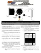
Wire Color Code
Yellow:
12v Constant Source (+) (un-switched)
Orange:
12v Switched Headlamp Source (+) (optional)
Red:
12v Ignition Source (+) (switched)
Green:
Fuel Level Sensor Signal Wire
Black:
Vehicle Ground (-)
1. Disconnect the vehicle’s negative battery cable.
Connecting the Power Wire Harness
2. To make the wiring of your gauges easier you can purchase an
expandable circuit. This component easily fits into your fuse panel and
provides an additional fused power wire for accessories such as gauges.
The expandable circuit is available for purchase at www.GlowShift.com.
3. Using automotive grade wiring (18 gauge); connect the yellow wire to a
positive 12 volt constant (un-switched) source either on the vehicle or in
the fuse box.
Note: If you are connecting the yellow wire directly to the
battery, you MUST install a 3 amp fuse within 6-8 inches of the
battery connection.
4. Using automotive grade wiring (18 gauge); connect the red wire to a
positive 12 volt ignition (switched) source. It may be connected to the
fuse panel, an accessory wire, or any positive 12 volt source that turns on
and off with the ignition.
5. Using automotive grade wiring (18 gauge); connect the black wire to
any good (unpainted) ground connection. You may also route a wire
directly to the negative side of the vehicle’s battery.
6. The Night Time Dimming feature decreases the brightness of the gauge
face by 30%. Connect the orange wire to the 12 volt positive headlamp
source. This allows the mode to be activated when the headlights come on.
This step is optional and will not affect operation of the gauge if it is
omitted.
Note: Do not connect the orange wire to a dimmer wheel. This
will cause the gauge lighting to flicker.
7. Run the green sensor wire from the back of the gauge through the
firewall to the vehicle’s fuel level sensor.
Note: Be sure to use a grommet when routing the wires
through the firewall to protect them from stripping and
damage.
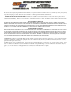
8. Use the Fuel Level Sensor Sensitivity Switch on the back of the gauge
to set the correct ohm (Ω) value scale to match the rating of the vehicle’s
fuel level sensor. Use the chart below to reference the correct setting that
applies closest to the values of your sensor. Please verify settings with a
repair manual or a dealer before installation.
If you need to change the ohm selection, you must remove
power from the gauge, make your selection, and then reapply
power to the gauge for proper calibration.
Be sure that your factory fuel level sensor is properly
grounded. You may have to add a secondary ground to
ensure it is properly grounded.
“Empty”
Ohm
Value
“Full”
Ohm
Value
Switch #
N/A
N/A
0
73 Ω
10 Ω
1
16 Ω
158 Ω
2
0 Ω
30 Ω
3
0 Ω
90 Ω
4
240 Ω
33 Ω
5
107.5 Ω
7 Ω
6
131 Ω
12 Ω
7
0 Ω
120 Ω
8
10 Ω
180 Ω
9
9. Reconnect the vehicle's negative battery cable.
If your gauge(s) do not illuminate or do not recall your last
saved color, your switched and un-switched sources are
reversed.
If your gauge(s) only illuminate red then the yellow wire for
constant source is not connected properly.
Be sure all of your wiring is correct to ensure proper gauge
operation.