
Owner manual


G D 9 5 20 I N S T RU CT IO N M A N UA L PAG E 5
2. Fit replacement fill strips as supplied into top and
bottom frame edges.
3. Mount your unit into the bulkhead. Use supplied spare
screw caps to cover screw heads.
ELECTRICAL WIRING
DC Connections
Caution: The GD9520 is designed for vessels with a
12 Volt negative ground electrical system only!
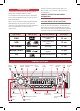
Referring to the wiring diagram below:
1. Connect the Yellow wire directly to the positive terminal
of the vessel’s battery, or to a point that has +12 Volts
available at all times. This lead maintains the memories
within the GD9520 and is the main power source for
the unit.
2. Connect the RED wire to the vessels +12 V supply via
an appropriate isolating switch or circuit breaker. This
lead enables the radio to be switched ON and OFF.
Alternatively, this wire can be connected directly to the
battery’s positive terminal and the G
D9520 switched ON
and OFF using it’s own controls.
3.
Connect the BLACK wire to the battery’s negative
terminal
or to the common negative bus in the electrical system.
Important: Your GD9520 is able to maintain it’s
memories when it is switched off using the PWR button by
drawing power directly from your battery via the YELLOW
‘MEMORY 12 V+’ lead. Although the memory backup
current is very small (about 20 mA) it may eventually
discharge your battery if left connected indefinitely. The
time taken to completely discharge your battery could vary
depending on its Amp-hour rating and battery condition.
If you do not run your boat’s motor regularly or your battery
is not kept charged between outings (e.g. Solar or wind
charger), we recommend you disconnect the YELLOW lead
each time you secure or trail your boat. This is easily done
by connecting the YELLOW ‘MEMORY 12 V+’ lead via a
Master switch, which can be switched off after each outing.
This will mean you will lose all your preset station memories
and clock settings.
Speaker Connections
When connecting the speakers, observe the correct polarity
as
shown in the diagram below. Incorrect polarity will result in a
reduction of bass response and Stereo effect. The use of speakers
with an impedance of less that 4 Ohms is not recommended, as
they will cause excessive loading of the GD9520’s output circuit
and may result with the radio overheating.
Ca
ution: The GD9520 is a four-speaker system that
requires 2 separate wires for each speaker.
A range of GME speakers are available from your local
G
ME retailer.
Fill Strips
Screw
Caps
R
EAR LEFT – GREEN/BLACK
REAR LEFT + GREEN
FRONT LEFT – WHITE/BLACK
FRONT LEFT + WHITE
REAR RIGHT – PURPLE/BLACK
REAR RIGHT + PURPLE
FRONT RIGHT – GREY/BLACK
FRONT RIGHT + GRE
Y
YELLOW
BLACK
BLACK
Front Audio Out
Rear Audio Out
GREY
Video In
Video Out
Digital Audio
Coaxial Out
Lch WHITE
Rch RED
Lch WHITE
Rch RED
Antenna
Connector
BLACK