GR200 AM/FM/VHF MARINE BROADCAST RADIO INSTRUCTION MANUAL
CONTENTS FEATURES...............................................................................................................3 ACCESSORIES SUPPLIED..........................................................................................3 OPTIONAL ACCESSORIES.........................................................................................3 COMPLIANCE.........................................................................................................4 LISTENING TO FM IN YOUR BOAT..............
FEATURES • Compact design with bracket or flush mounting options • Ingress Protection to IP55* • 7 bands (LW, SW, AM1, AM2, FM1, FM2, VHF) • 6 preset frequency memories per band • Simple push button controls.
COMPLIANCE This device complies with AS/NZS 61000.6.3:2007. This device complies with part 15 of the FCC rules. Operation is subject to the condition that this device does not cause harmful interference. LISTENING TO FM IN YOUR BOAT The majority of FM broadcasts are music programs. Compared with AM signals, FM signals have a wider dynamic range, are relatively immune to noise and provide virtually distortion free music reproduction.
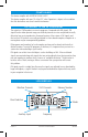
CONTROLS POWER KEY Press and hold the Power key to turn the GR200 ON or OFF. While the radio is ON briefly press the Power key to toggle the audio mute function. ‘MUTE’ will flash on the display when the mute function is activated. MODE KEY (M) The Mode key provides access to the Volume, Bass, Treble, Balance, Frequency Adjustment, Automatic Memory Store (AMS) and Local/DX settings. The Mode selection will automatically return to the Volume setting 20 seconds after the last key press.
UP/DOWN KEYS The Up and Down keys are used to adjust functions selected using the Mode key. MEMORY KEYS Six memory keys are provided for storage and retrieval of station memories. OPERATION TURNING THE GR200 ON AND OFF To switch the GR200 on, press and hold the The radio will turn ON. key for two seconds. To switch the GR200 off, press and hold the The radio will turn OFF. key for two seconds.
Adjusting the Treble To select the treble mode, briefly press the Mode key repeatedly until ‘TRE’ is displayed on the right of the LCD. To adjust the treble, press the or key. Pressing the key will increase the treble while pressing the key will decrease the treble. The treble setting will be displayed on the LCD. Minimum treble setting displays a value of -7 with a maximum treble setting of +7. A setting of 0 indicates a flat treble response.
TUNING FOR STATIONS Selecting the Frequency Band The GR200 has 7 selectable frequency bands plus an Auxiliary audio input. The frequency bands available are Long Wave (LW), Short Wave (SW), Medium Wave (AM1 and AM2), FM (FM1 and FM2) and VHF Marine (VHF). The Auxiliary input mode allows audio from external sources such as MP3 players to be connected via a 3.5 mm socket lead on the rear panel. To select the desired frequency band (or the Auxiliary input) briefly press the Band key.
MEMORY KEYS The GR200 has 6 preset memory keys which allow up to 6 frequencies to be stored and recalled within each band. Because there are two identical AM bands and two identical FM bands, this allows 12 AM and 12 FM preset memories. The memories can be stored either manually or automatically. Manually Locating and Storing Station Frequencies in the Preset Memories 1. Press the Band key repeatedly until the required band is selected. 2.
LOCAL/DX MODE The Local/DX mode controls the receiver’s sensitivity when in the FM mode. The GR200 can be set to high sensitivity for long distance reception (DX) or low sensitivity for local reception (LOC). Briefly press the Mode key repeatedly until AMS is selected then press ONCE more to access the LOC function. Press the or keys to toggle LOCAL or DX modes. A solid LOC symbol on the display indicates LOCAL mode is selected. If the LOC symbol is flashing then DX mode is selected.
MOUNTING THE GR200 The GR200 is designed to be mounted in several different ways to enable it to be installed in the most convenient position. The GR200 is designed to meet IP55 Standard (Refer: www.gme.net.au/IPRatings). A location should be selected which provides the best viewing angle for the display. For best results select a location that is free from excessive vibration and continuous direct sunlight.
ELECTRICAL WIRING The GR200 is suitable for either negative or positive ground systems. NOTE: The GR200 has an over voltage detector to indicate when excessive voltage is being applied to the radio. The over voltage detector is triggered when the voltage being applied to the power leads exceeds 18 volts DC. If this happens, the words ‘hi dc’ will flash on the display. If the voltage exceeds 21 volts DC, the radio will automatically shut down.
The GR200 is supplied with two speaker adapter leads which are designed to accept the standard bullet connectors found on some GME marine speakers and most marine and automotive speaker cables. The plugs on the speaker adapters plug into the matching the sockets on the rear of the GR200. The plugs are fitted with protective flexible covers. When connecting the speakers, observe the correct polarity as shown in the diagram. Incorrect polarity will result in a reduction of bass response and stereo effect.
SPECIFICATIONS* General Complies with: AS/NZS 61000.6.3:2007 Frequency Range: LW, MW, SW, VHF, AM and FM Channel Set: Broadcast Radio Bands and VHF Marine Band Scan Speed: 100 ms/channel Supply Voltage Range: 10.8 – 15.
External connections DC Supply: 2 Pin polarised plug socket External Speakers: 3.5 mm mini phone jacks Auxiliary input: 3.5 mm stereo phone jack *All specifications are typical and subject to change without notice or obligation. STANDARD COMMUNICATIONS WARRANTY AGAINST DEFECTS This warranty against defects is given by Standard Communications Pty Ltd ACN 000 346 814 (We, us, our or GME). Our contact details are set out in clause 2.7. This warranty statement only applies to products purchased in Australia.
we agree to supply those services again at no extra charge to you. 2.6 To make a warranty claim you must before the end of the applicable warranty period (see warranty table), at your own cost, return the goods you allege are defective, provide written details of the defect, and give us an original or copy of the sales invoice or some other evidence showing details of the transaction. 2.7 Send your claim to: Standard Communications Pty Ltd. Unit B, 22-24 College Street, Gladesville, NSW 2111, Australia.
MK600 IN DASH FITTING INSTRUCTIONS REAR VIEW Contents: 2 S/S brackets 2 adhesive backing strips 4 S/S self tapping screws 4 S/S metal-thread screws Adhesive Backing Plate ✂ D.N. 42261-3 P.N. 310226 Figure 1 6.0 Radius Cut Out 156 mm x 58 mm Place the GX600 through the hole. If the dashboard is subject to water spray it may be beneficial to apply a thin bead of sealant to prevent any water ingress between the body of the radio and the dashboard.
66 mm 165 mm Mark and cut a hole 66 mm (h) by 165 mm (w), allowing for clearance of the two mounting screws holding the radio to the surround. Use a 10 mm drill bit to form the radius of the corners and an 8 mm drill bit for the clearance of the mounting screws. 10 mm Drill Bit MK001B INSTALLATION - CUTTING TEMPLATE 2.
66 mm 165 mm Mark and cut a hole 66 mm (h) by 165 mm (w), allowing for clearance of the two mounting screws holding the radio to the surround. Use a 10 mm drill bit to form the radius of the corners and an 8 mm drill bit for the clearance of the mounting screws. 10 mm Drill Bit MK001W INSTALLATION - CUTTING TEMPLATE 2.