GR9200 SERIES MARINE STEREO SYSTEMS GR9220W • GR9220B GR9240W • GR9240B INSTRUCTION MANUAL
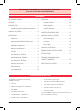
gme strongly recommends that you keep this manual in a safe place for future reference CONTENTS ACCESSORIES SUPPLIED. . . . . . . . . . . . . . . . . . . . . 2 OPERATION . . . . . . . . . . . . . . . . . . . . . . . . . . . . . 10 Features. . . . . . . . . . . . . . . . . . . . . . . . . . . . . . . . 3 General Functions. . . . . . . . . . . . . . . . . . . . . . 10 INTRODUCTION . . . . . . . . . . .
features • • • • MP3 via CD/USB/SD card and auxiliary input Detachable front face panel 4 x 45 Watt power output onformally coated PCBs for protection against C the harsh marine environment. • Rugged and weather resistant case, made from high impact UV protected plastics. • ultiple mounting options - flush or M bracket mount depending on model. • Backlit LCD screen Pod* connectivity via optional • iinterconnect cable • Available in black or white *iPod is a trademark of Apple Computer Inc.
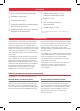
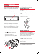
CONTROL LOCATIONS 17 5 1 12 16 8 21 6 10 GR9200 4x45 Watts D-DN 15 4 7 14 19 20 11 3 2 13 9 18 1 Power On/Off 12 Eject 2 Volume Control 13 Auto Music Search 3 Select 14 Loudness 15 Release Button Mute 16 LCD Display Clock/Time Selector 17 CD Slot Mode Switch 18 Auxiliary Input LOC/DX Selector 19 USB Input Preset memory Keys and CD/MP3 functions.
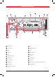
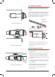
To refit the face panel INSTALLATION PRECAUTIONS If you are connecting your GR9200 for the first time or have just reconnected your boat battery and you are experiencing problems with the unit’s operation, we suggest you try resetting the unit. The reset button is located under the removable face panel (see below for instructions). Gently press the reset button with a paper clip or similar object. You can then refit the face panel. Reset Button 1.
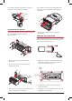
Flush Mounting - GR9220 The GR9220 can be neatly flush mounted into a panel or bulkhead so that just the controls and the protective cover are visible. Using the template provided, select a suitable location on a panel or bulkhead. Examine behind the panel to determine the best method of support. If the thickness of the panel is not sufficient to support the unit, it will be necessary to use the strap supplied (see following diagrams).
For overhead mounting, the GME logos on the side of each bracket can be rotated as shown right. Your GR9240 can now be flush mounted. Replacement screw caps have been provided to cover the exposed screw heads. Press from back Turn Flush mounting - gr9240 Although the GR9240 is a bracket mounted unit, it can be flush mounted by following the disassembly instructions below. * Note rubber mounting gasket not supplied with GR9240 unit.
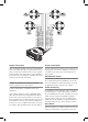
Electrical Wiring DC Connections Caution: The GR9200 is designed for vessels with a 12 Volt negative ground electrical system only! Referring to the wiring diagram on this page: 1. C onnect the YELLOW wire directly to the positive terminal of the vessel’s battery, or to a point that has +12 Volts available at all times. This lead maintains the memories within the GR9200 and is the main power source for the unit. 2.
FRONT RIGHT + GREY FRONT RIGHT – GREY/BLACK REAR RIGHT + PURPLE REAR RIGHT – PURPLE/BLACK REAR LEFT – GREEN/BLACK REAR LEFT + GREEN FRONT LEFT – WHITE/BLACK FRONT LEFT + WHITE Speaker Connections Antenna Connections When connecting the speakers, observe the correct polarity as shown in the diagram above right. Incorrect polarity will result in a reduction of Bass response and stereo effect.
object (see PRECAUTIONS on page 5). This will ensure the GR9200 is ready to operate for the first time. If at any time the controls do not seem to work (after replacing the vessel’s battery for example), press the Reset button to reset the microcomputer inside the GR9200. Fuse Replacement If any of the fuses blow, replace them with a standard 30 mm 3 AG type of the same rating. If the fuse blows a second time contact your retailer.
CD/MP3 Operation NOTE: If all power is disconnected from the GR9200, the unit defaults to European frequency bands when reconnected. NOTE: The differences between bands is listed in the specifications at the rear of the manual. 10 Band Selector To select the required radio band (AM1, AM2 FM1 FM2 or FM3), sequentially press the BND button until the required band is selected. 11 Tuning/Selecting Tracks Manual Tuning To tune the radio manually, momentarily press the button to select the desired frequency.
11 Step to the Next Track To step immediately to the next track, press the button once. The next selected track will begin playing, press the button to advance to the start of successive tracks. To step immediately to the start of the track currently being played, press the button once. The current track will immediately restart. Press the button repeatedly to locate the start of previous tracks. recorder you are using to write your CDs for the finalisation process.
CONfiguration menu table Function Options Description Beep On I Off Enables/disables confirmation beeps on key presses Audio Response User Set I Flat I Classic I Rock I Pop Selects preset audio responses for various music styles. Select ‘User Set’ if you prefer to manually adjust the audio response using the Bass/Treble controls. Volume Last I Default Set the volume level used when the radio is turned on. Select ‘ Last ’ to restore the volume to the last used setting.
AUXILIARY INPUTS & OUTPUTS To maximise the owner’s listening flexibility and pleasure the GR9200 series have several auxiliary inputs and outputs. Front Panel Inputs There are standard USB and SD Card inputs located on the front panel. USB The USB Input accepts USB flash memory drives loaded with MP3 files. When using the USB input we recommend using the USB adapter AD003 supplied as a standard accessory with your GR9200.
OPTIONAL ACCESSORIES There are a number of high quality GME accessories available to enhance your marine entertainment experience. These accessories are available through your local GME retailer, should you have any difficulty in obtaining any GME accessory, please call or email your local GME Sales Office (within Australia and New Zealand). Contact details are listed on the back page of this manual.
GR9200 Trouble Shooting Guide Symptom No Power. C ause Solution Vessel’s battery switch is not on. Check master switch if fitted. One of the fuses is blown. Replace the damaged fuse with the correct value. Error messages displayed on LCD or functions not operating. Microprocessor lock up. Press Reset Button. Poor radio reception. Damaged or incorrect type of antenna. Check antenna and replace if necessary. CD cannot be loaded. There is already a CD in the player.
specifications* FM Radio audio amplifier Frequency Range: 87.5 - 108 MHz (Eu./Aust./N.Z.) 87.5 - 107.9 MHz (U.S.A.) Frequency Step: 50 kHz (Eu./Aust./NZ 200 kHz /USA Audio Output: ( 4 channels x 45 W Peak = 180 W Peak) @ 10% THD. Speaker Impedance: 4 Ohm Bass Adjustment Range: +/- 10 dB Intermediate Frequency: 10.
Standard communications contract warranty 1. STATUTORY WARRANTIES 2.4 1.1 The Trade Practices Act Part V, Division 2A and other legislation imply conditions, warranties and other obligations on us to consumers that cannot be excluded, restricted or modified. Those provisions apply to the extent required by law. 1.2 We exclude all other conditions, warranties and obligations which would otherwise be implied concerning the activities covered by this agreement. 1.
GR9200 series i n s t ru c t i o n m a n ua l PA G E 1 9
Part No: 310443 Drawing No: 44415-2 INSTRUC TION MANUAL GR9200 SERIES