® powered by GP-FLEX-100 GP-FLEX-200 GP-FLEX-100E Solar Flex User’s Manual MC4 Branch Connectors Solar Controller Solar Kit GP-FLEX-100 Solar Expansion Kit GP-FLEX-100E
GP-FLEX-100 GP-FLEX-200 GP-FLEX-100E Table of Contents 1.0 General Information.................................................................................................................................................................................. 3 1.1 How Does a Go Power! Solar Charging Kit Work?.................................................................................................................................. 3 1.2 Warnings..........................................................
GP-FLEX-100 GP-FLEX-200 GP-FLEX-100E 1.0 General Information Congratulations on purchasing your Go Power! Solar FlexTM Kit. You have chosen a clean, quiet and sustainable power source. Go Power! Solar Charging Kits allow you to enjoy the luxuries that electricity provides, without hooking up to shore power, by keeping your batteries charged.
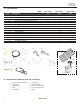
GP-FLEX-100 GP-FLEX-200 GP-FLEX-100E 1.3 Parts Checklist MODEL: ITEM# GP-FLEX-100 GP-FLEX-200 GP-FLEX-100E QTY QTY QTY 01 DESCRIPTION Ring Terminal Battery Connector 2 2 0 02 50’ MC4 Cable with Male and Female MC4 Connectors 1 1 0 03 Tie Wrap 6 6 6 04 Male (positive) MC4 Parallel Branch Connector 0 1 1 05 Female (negative) MC4 Parallel Branch Connector 0 1 1 06 #10 x 1” Wood Screws 6 12 6 07 #10 x 1.
GP-FLEX-100 GP-FLEX-200 GP-FLEX-100E 2.0 Wiring Modules with MC4 Cables Solar Kits with MC4 cables contain a potted or sealed junction box with a positive and negative MC4 connector. This is referred to as an MC4 junction box. MC4 connectors are either positive or negative and each connector has its polarity symbol embossed close to the connection point. To extend a cable from an MC4 junction box, a polarity opposite connector must be used. E.G.
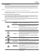
GP-FLEX-100 GP-FLEX-200 GP-FLEX-100E 5.0 Solar Controller Installing The GP-PWM-30 Solar Controller The GP-PWM-30 is included in all Go Power! Solar FlexTM Kits mentioned in this manual, except for the GP-FLEX-100E Expansion Kit. Fuse The GP-PWM-30 protects the battery from overcharging. A condensed version of the installation instructions appear below. Please read the full installation manual included with the GP-PWM-30 Solar Controller before installing. Positive Connection Negative Connection 1.
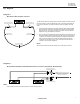
GP-FLEX-100 GP-FLEX-200 GP-FLEX-100E 8.0 Diagrams Diagram 1: MC4 Power Cabels For Solar FlexTM Kits JUNCTION BOX Male (positive) MC4 Junction Box Connection Female (negative) MC4 Junction Box Connection Negative MC4 Cable Conductor Positive MC4 Cable Conductor Cut 50’ wire in half to make two 25’ cables The MC4 power cable is usually the final connection between the solar array and the solar controller.
GP-FLEX-100 GP-FLEX-200 GP-FLEX-100E ® powered by © 2014 Go Power! By Carmanah Technologies Document: GP_MAN_GP-SOLAR-FELX_ 100_200_100E_RevB 8 gpelectric.